CHASSIS
3-21
WARNING
EWA13090
• Use only the designated brake fluid. Other
brake fluids may cause the rubber seals to
deteriorate, causing leakage and poor
brake performance.
• Refill with the same type of brake fluid that
is already in the system. Mixing brake fluids
may result in a harmful chemical reaction,
leading to poor brake performance.
• When refilling, be careful that water does
not enter the brake fluid reservoir. Water
will significantly lower the boiling point of
the brake fluid and could cause vapor lock.
CAUTION:
ECA13540
Brake fluid may damage painted surfaces
and plastic parts. Therefore, always clean up
any spilt brake fluid immediately.
NOTE:
In order to ensure a correct reading of the brake
fluid level, make sure the top of the brake fluid
reservoir is horizontal.
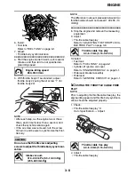
4. Install:
• Rider seat
Refer to “GENERAL CHASSIS” on page 4-1.
EAS21250
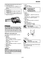
CHECKING THE FRONT BRAKE PADS
The following procedure applies to all of the
brake pads.
1. Operate the brake.
2. Check:
• Front brake pad
Wear indicator grooves “1” almost disap-
peared
→
Replace the brake pads as a set.
Refer to “FRONT BRAKE” on page 4-31.
EAS21260
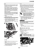
CHECKING THE REAR BRAKE PADS
The following procedure applies to all of the
brake pads.
1. Operate the brake.
2. Check:
• Rear brake pad
Wear indicators “1” almost touch the brake
disc
→
Replace the brake pads as a set.
Refer to “REAR BRAKE” on page 4-43.
EAS21280
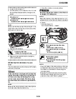
CHECKING THE FRONT BRAKE HOSES
The following procedure applies to all of the
brake hoses and brake hose clamps.
1. Check:
• Brake hoses “1”
Cracks/damage/wear
→
Replace.
A. Front brake
B. Rear brake
a
B
1
1
Summary of Contents for XV19SW 2006
Page 6: ......
Page 8: ......
Page 24: ...SPECIAL TOOLS 1 15...
Page 55: ...LUBRICATION POINTS AND LUBRICANT TYPES 2 30...
Page 60: ...LUBRICATION SYSTEM CHART AND DIAGRAMS 2 35 D D B B D D C C A A B C C B 3 2 1 3 4 6 7 6 7 5...
Page 62: ...LUBRICATION SYSTEM CHART AND DIAGRAMS 2 37 A A A A 1 3 2 4...
Page 64: ...LUBRICATION SYSTEM CHART AND DIAGRAMS 2 39 A 1 2 3 4...
Page 66: ...LUBRICATION SYSTEM CHART AND DIAGRAMS 2 41 A A A 1 5 5 1 3 2 4 B B B B...
Page 68: ...LUBRICATION SYSTEM CHART AND DIAGRAMS 2 43 1 2...
Page 69: ...LUBRICATION SYSTEM CHART AND DIAGRAMS 2 44 1 Transfer gear oil pump 2 Middle driven shaft...
Page 78: ...CABLE ROUTING 2 53...
Page 86: ...CABLE ROUTING 2 61...
Page 89: ......
Page 122: ...ELECTRICAL SYSTEM 3 33 a b 1...
Page 125: ......


