


CHASSIS
3-22
2. Check:
• Brake hose clamps
Loose
→
Tighten the clamp bolt.
3. Hold the vehicle upright and apply the brake
several times.
4. Check:
• Brake hoses
Brake fluid leakage
→
Replace the damaged
hose.
Refer to “FRONT BRAKE” on page 4-31.
EAS21290
CHECKING THE REAR BRAKE HOSES
1. Remove:
• Rider seat
Refer to “GENERAL CHASSIS” on page 4-1.
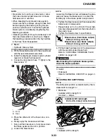
2. Check:
• Brake hoses “1”
Cracks/damage/wear
→
Replace.
3. Check:
• Brake hose clamp
Loose connection
→
Tighten the clamp bolt.
4. Check:
• Brake hose guide
Loose
→
Tighten the guide bolt.
5. Hold the vehicle upright and apply the brake
several times.
6. Check:
• Brake hoses
Brake fluid leakage
→
Replace the damaged
hose.
Refer to “REAR BRAKE” on page 4-43.
EAS21330
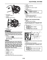
ADJUSTING THE REAR BRAKE LIGHT
SWITCH
NOTE:
The rear brake light switch is operated by move-
ment of the brake pedal. The rear brake light
switch is properly adjusted when the brake light
comes on just before the braking effect starts.
1. Check:
• Rear brake light operation timing
Incorrect
→
Adjust.
2. Adjust:
• Rear brake light operation timing
▼▼▼
▼
▼
▼▼▼
▼
▼
▼▼▼
▼
▼
▼▼▼
▼
▼
▼▼▼
▼
▼
▼▼▼
▼
▼▼▼
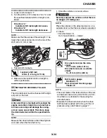
a. Hold the main body “1” of the rear brake light
switch so that it does not rotate and turn the
adjusting nut “2” in direction “a” or “b” until the
rear brake light comes on at the proper time.
▲▲▲
▲
▲
▲▲▲
▲
▲
▲▲▲
▲
▲
▲▲▲
▲
▲
▲▲▲
▲
▲
▲▲▲
▲
▲▲▲
EAS21350
BLEEDING THE HYDRAULIC BRAKE
SYSTEM
WARNING
EWA13100
Bleed the hydraulic brake system whenever:
• the system is disassembled.
• a brake hose is loosened, disconnected or
replaced.
• the brake fluid level is very low.
• brake operation is faulty.
1. Remove:
• Rider seat
Refer to “GENERAL CHASSIS” on page 4-1.
1
1
1
1
1
Direction “a”
Brake light comes on sooner.
Direction “b”
Brake light comes on later.
1
2
a
b
Summary of Contents for XV19SW 2006
Page 6: ......
Page 8: ......
Page 24: ...SPECIAL TOOLS 1 15...
Page 55: ...LUBRICATION POINTS AND LUBRICANT TYPES 2 30...
Page 60: ...LUBRICATION SYSTEM CHART AND DIAGRAMS 2 35 D D B B D D C C A A B C C B 3 2 1 3 4 6 7 6 7 5...
Page 62: ...LUBRICATION SYSTEM CHART AND DIAGRAMS 2 37 A A A A 1 3 2 4...
Page 64: ...LUBRICATION SYSTEM CHART AND DIAGRAMS 2 39 A 1 2 3 4...
Page 66: ...LUBRICATION SYSTEM CHART AND DIAGRAMS 2 41 A A A 1 5 5 1 3 2 4 B B B B...
Page 68: ...LUBRICATION SYSTEM CHART AND DIAGRAMS 2 43 1 2...
Page 69: ...LUBRICATION SYSTEM CHART AND DIAGRAMS 2 44 1 Transfer gear oil pump 2 Middle driven shaft...
Page 78: ...CABLE ROUTING 2 53...
Page 86: ...CABLE ROUTING 2 61...
Page 89: ......
Page 122: ...ELECTRICAL SYSTEM 3 33 a b 1...
Page 125: ......