


CHASSIS
3-24
▼▼▼
▼
▼
▼▼▼
▼
▼
▼▼▼
▼
▼
▼▼▼
▼
▼
▼▼▼
▼
▼
▼▼▼
▼
▼▼▼
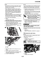
a. Loosen both locknuts “1”.
b. Turn the shift rod “2” in direction “a” or “b” until
the specified installed shift rod length is ob-
tained.
NOTE:
Make sure that the exposed thread length “c” be-
tween the locknut and joint on both ends of the
shift rod is 10 mm or less.
c. Tighten both locknuts.
d. Make sure the installed shift rod length is
within specification.
▲▲▲
▲
▲
▲▲▲
▲
▲
▲▲▲
▲
▲
▲▲▲
▲
▲
▲▲▲
▲
▲
▲▲▲
▲
▲▲▲
EAS21430
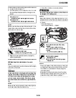
ADJUSTING THE DRIVE BELT SLACK
NOTE:
The drive belt slack must be checked at the tight-
est point on the belt.
CAUTION:
ECA14950
A drive belt that is too tight will overload the
engine and other vital parts, and one that is
too loose can skip and damage the swing-
arm or cause an accident. Therefore, keep
the drive belt slack within the specified lim-
its.
NOTE:
Measure the drive belt slack when the engine is
cold, and when the drive belt is dry.
1. Stand the vehicle on a level surface.
WARNING
EWA13120
Securely support the vehicle so that there is
no danger of it falling over.
NOTE:
Place the vehicle on the sidestand and or on a
suitable stand so that the rear wheel is elevated.
2. Check:
• Drive belt slack “a”
Out of specification
→
Adjust.
NOTE:
• The level marks of the level window on the low-
er drive belt cover are in units of 5 mm (0.20 in).
Use them as a standard for measuring the
drive belt slack.
• Measure the drive belt slack when the drive
belt has been pushed with 4.5 kg (10 lbs) of
pressure using a belt tension gauge “1”.
Direction “a”
Installed shift rod length increases.
Direction “b”
Installed shift rod length decreases.
T
R
.
Locknut (shift rod)
12 Nm (1.2 m·kg, 8.7 ft·lb)
a
b
2
1
c
c
Drive belt slack (on the side-
stand)
7.5–13 mm (0.30–0.51 in)
Drive belt slack (on a suitable
stand)
14–21 mm (0.55–0.83 in)
Belt tension gauge
90890-03170
Rear drive belt tension gauge
YM-03170
a
Summary of Contents for XV19SW 2006
Page 6: ......
Page 8: ......
Page 24: ...SPECIAL TOOLS 1 15...
Page 55: ...LUBRICATION POINTS AND LUBRICANT TYPES 2 30...
Page 60: ...LUBRICATION SYSTEM CHART AND DIAGRAMS 2 35 D D B B D D C C A A B C C B 3 2 1 3 4 6 7 6 7 5...
Page 62: ...LUBRICATION SYSTEM CHART AND DIAGRAMS 2 37 A A A A 1 3 2 4...
Page 64: ...LUBRICATION SYSTEM CHART AND DIAGRAMS 2 39 A 1 2 3 4...
Page 66: ...LUBRICATION SYSTEM CHART AND DIAGRAMS 2 41 A A A 1 5 5 1 3 2 4 B B B B...
Page 68: ...LUBRICATION SYSTEM CHART AND DIAGRAMS 2 43 1 2...
Page 69: ...LUBRICATION SYSTEM CHART AND DIAGRAMS 2 44 1 Transfer gear oil pump 2 Middle driven shaft...
Page 78: ...CABLE ROUTING 2 53...
Page 86: ...CABLE ROUTING 2 61...
Page 89: ......
Page 122: ...ELECTRICAL SYSTEM 3 33 a b 1...
Page 125: ......