


ENGINE
3-18
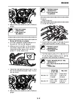
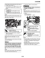
• Muffler “3”
• Muffler bracket “4”
Cracks/damage
→
Replace.
• Gaskets “5”
Exhaust gas leaks
→
Replace.
2. Check:
Tightening torque
• Front exhaust pipe nuts “6”
• Front exhaust pipe and rear exhaust pipe bolt
“7”
• Rear exhaust pipe nuts “8”
• Rear exhaust pipe and muffler bolt “9”
• Muffler and muffler bracket bolts “10”
• Muffler bracket and frame bolts “11”
EAS21090
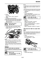
CHECKING THE CANISTER (for California
only)
1. Remove:
• Horn 1
Refer to “THROTTLE BODIES” on page 6-6.
2. Check:
• Canister “1”
• Canister purge hose “2”
• Canister breather hose “3”
• Fuel tank breather/overflow hose “4”
Cracks/damage
→
Replace.
3. Install:
• Horn 1
Refer to “THROTTLE BODIES” on page 6-6.
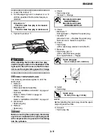
EAS21100
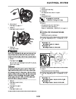
ADJUSTING THE EXUP CABLES
1. Remove:
• EXUP valve pulley cover “1”
2. Check:
• EXUP system operation
▼▼▼
▼
▼
▼▼▼
▼
▼
▼▼▼
▼
▼
▼▼▼
▼
▼
▼▼▼
▼
▼
▼▼▼
▼
▼▼▼
a. Turn the main switch to “ON”.
b. Check that the EXUP valve operates proper-
ly.
NOTE:
Check that the projection “a” on the EXUP valve
pulley contact the stopper “b” (fully-open posi-
tion) and the stopper “c” (fully-closed position).
T
R
.
Front exhaust pipe nut
20 Nm (2.0 m·kg, 14 ft·lb)
Front exhaust pipe and rear ex-
haust pipe bolt
20 Nm (2.0 m·kg, 14 ft·lb)
Rear exhaust pipe nut
24 Nm (2.4 m·kg, 17 ft·lb)
Rear exhaust pipe and muffler
bolt
20 Nm (2.0 m·kg, 14 ft·lb)
Muffler and muffler bracket bolt
29 Nm (2.9 m·kg, 21 ft·lb)
Muffler bracket and frame bolt
53 Nm (5.3 m·kg, 38 ft·lb)
LOCTITE
®
10
11
3
4
8
9
5
2
7
5
5
1
6
5
LT
4
1
3
2
1
Summary of Contents for XV19SW 2006
Page 6: ......
Page 8: ......
Page 24: ...SPECIAL TOOLS 1 15...
Page 55: ...LUBRICATION POINTS AND LUBRICANT TYPES 2 30...
Page 60: ...LUBRICATION SYSTEM CHART AND DIAGRAMS 2 35 D D B B D D C C A A B C C B 3 2 1 3 4 6 7 6 7 5...
Page 62: ...LUBRICATION SYSTEM CHART AND DIAGRAMS 2 37 A A A A 1 3 2 4...
Page 64: ...LUBRICATION SYSTEM CHART AND DIAGRAMS 2 39 A 1 2 3 4...
Page 66: ...LUBRICATION SYSTEM CHART AND DIAGRAMS 2 41 A A A 1 5 5 1 3 2 4 B B B B...
Page 68: ...LUBRICATION SYSTEM CHART AND DIAGRAMS 2 43 1 2...
Page 69: ...LUBRICATION SYSTEM CHART AND DIAGRAMS 2 44 1 Transfer gear oil pump 2 Middle driven shaft...
Page 78: ...CABLE ROUTING 2 53...
Page 86: ...CABLE ROUTING 2 61...
Page 89: ......
Page 122: ...ELECTRICAL SYSTEM 3 33 a b 1...
Page 125: ......