ENGINE
3-19
▲▲▲
▲
▲
▲▲▲
▲
▲
▲▲▲
▲
▲
▲▲▲
▲
▲
▲▲▲
▲
▲
▲▲▲
▲
▲▲▲
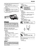
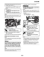
3. Check:
• EXUP cable free play (at the EXUP valve pul-
ley) “a” and “b”
4. Adjust:
• EXUP cable free play
▼▼▼
▼
▼
▼▼▼
▼
▼
▼▼▼
▼
▼
▼▼▼
▼
▼
▼▼▼
▼
▼
▼▼▼
▼
▼▼▼
a. Loosen both locknuts “1”.
b. Turn both adjusting bolts “2” in or out until the
specification.
c. Tighten both locknuts.
d. Turn the main switch to “ON” and check that
the projection “c” on the EXUP valve pulley
contacts the stoppers (fully open and fully
closed positions), then stops between the
lines “d” on the cable holder.
▲▲▲
▲
▲
▲▲▲
▲
▲
▲▲▲
▲
▲
▲▲▲
▲
▲
▲▲▲
▲
▲
▲▲▲
▲
▲▲▲
5. Install:
• EXUP valve pulley cover
EXUP cable free play (at the
EXUP valve pulley)
a: 3 mm (0.12 in) or less
b: 3 mm (0.12 in) or less
Turn in “a”
→
Free play is increased.
Turn out “b”
→
Free play is decreased.
b
c
a
b
a
1
T
R
.
EXUP valve pulley cover bolt
7 Nm (0.7 m·kg, 5.1 ft·lb)
a
b
a
b
2
2
d
c
Summary of Contents for XV19SW 2006
Page 6: ......
Page 8: ......
Page 24: ...SPECIAL TOOLS 1 15...
Page 55: ...LUBRICATION POINTS AND LUBRICANT TYPES 2 30...
Page 60: ...LUBRICATION SYSTEM CHART AND DIAGRAMS 2 35 D D B B D D C C A A B C C B 3 2 1 3 4 6 7 6 7 5...
Page 62: ...LUBRICATION SYSTEM CHART AND DIAGRAMS 2 37 A A A A 1 3 2 4...
Page 64: ...LUBRICATION SYSTEM CHART AND DIAGRAMS 2 39 A 1 2 3 4...
Page 66: ...LUBRICATION SYSTEM CHART AND DIAGRAMS 2 41 A A A 1 5 5 1 3 2 4 B B B B...
Page 68: ...LUBRICATION SYSTEM CHART AND DIAGRAMS 2 43 1 2...
Page 69: ...LUBRICATION SYSTEM CHART AND DIAGRAMS 2 44 1 Transfer gear oil pump 2 Middle driven shaft...
Page 78: ...CABLE ROUTING 2 53...
Page 86: ...CABLE ROUTING 2 61...
Page 89: ......
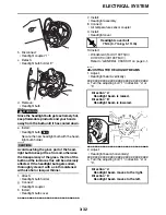
Page 122: ...ELECTRICAL SYSTEM 3 33 a b 1...
Page 125: ......


