10/00
2-47
Phaser 790/DocuColor 2006
004-320
Status Indicator RAPs
Initial Issue
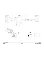
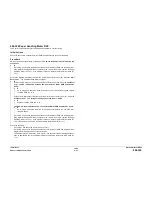
004-320 Paper Handling Motor RAP
The Control Logic detected that the Paper Handling Motor is not functioning.
Initial Actions
Check the connectors on the Drive Motor PWB. Ensure that they are correctly seated.
Procedure
Switch off the power then switch on the power. The 04-320 fault code is declared at the end
of self-test.
Y
N
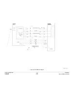
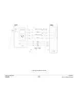
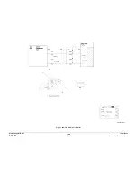
Go to Flag 2 and check the harness between the Drive Motor PWB and the Paper Han-
dling Motor for damaged wires or connector pins. If the wires are OK, replace the Paper
Handling Motor (PL 10.1). If the problem continues, replace the Drive Motor PWB (PL
10.1).
Access the Digital Output (DO) test from the Control Panel. Enter code [53]. Press the Item/
Enter button. The Paper Handling Motor energizes.
Y
N
Access the DO Stop Test from the Control Panel. Enter code [53]. Press the Item/Enter
button. +5 VDC is measured between J50-2 on the Drive Motor PWB and machine
frame.
Y
N
Go to Flag 3 and check the wires for an open circuit. If the wires are good, replace
the MCU PWB (PL 11.2).
Access the Digital Output (DO) test from the Control Panel. Enter code [53]. Press the
Item/Enter button. The voltage at J50-2 goes to less than +1.0 VDC
Y
N
Replace the MCU PWB (PL 11.2).
+24 VDC is measured between J49-2 on the Drive Motor PWB and machine frame.
Y
N
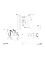
Go to Flag 4 and check the wires for an open circuit (refer to the +24 VDC Inter-
locked Wirenet).
Go to Flag 2 and check the harness between the Drive Motor PWB and the Paper Han-
dling Motor for damaged wires or connector pins. If the wires are OK, replace the Paper
Handling Motor (PL 10.1). If the problem continues, replace the Drive Motor PWB (PL
10.1). If the problem can not be resolved, replace the MCU PWB (PL 11.1)
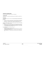
Check the following:
•
Go to Flag 1 and check the wire for an open circuit.
•
Go to Flag 2 and check the harness between the Drive Motor PWB and the Paper Han-
dling Motor for damaged wires or connector pins.
•
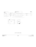
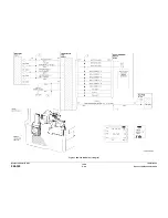
The problem may be intermittent. Go to Figure 1 and check for loose or damaged connec-
tions or damaged wires. If the problem persists, replace the replace the MCU PWB (PL
11.2).
Summary of Contents for Phaser 790
Page 4: ...10 00 ii Phaser 790 DocuColor 2006 Initial Issue Introduction...
Page 10: ...10 00 1 2 Phaser 790 DocuColor 2006 Initial Issue Service Call Procedures...
Page 46: ...10 00 2 32 Phaser 790 DocuColor 2006 002 702 Initial Issue Status Indicator RAPs...
Page 80: ...10 00 2 66 Phaser 790 DocuColor 2006 005 704 Initial Issue Status Indicator RAPs...
Page 130: ...10 00 2 116 Phaser 790 DocuColor 2006 007 713 Initial Issue Status Indicator RAPs...
Page 150: ...10 00 2 136 Phaser 790 DocuColor 2006 008 707 Initial Issue Status Indicator RAPs...
Page 180: ...10 00 2 166 Phaser 790 DocuColor 2006 009 704 Initial Issue Status Indicator RAPs...
Page 193: ...10 00 2 179 Phaser 790 DocuColor 2006 010 700 Status Indicator RAPs Initial Issue...
Page 204: ...10 00 2 190 Phaser 790 DocuColor 2006 010 705 Initial Issue Status Indicator RAPs...
Page 220: ...10 00 2 206 Phaser 790 DocuColor 2006 011 706 Initial Issue Status Indicator RAPs...
Page 226: ...10 00 2 212 Phaser 790 DocuColor 2006 016 370 Initial Issue Status Indicator RAPs...
Page 234: ...10 00 3 2 Phaser 790 DocuColor 2006 Initial Issue Image Quality...
Page 245: ...10 00 3 13 Phaser 790 DocuColor 2006 IQ8 Image Quality Initial Issue...
Page 254: ...10 00 3 22 Phaser 790 DocuColor 2006 IQ18 Initial Issue Image Quality...
Page 258: ...10 00 4 4 Phaser 790 DocuColor 2006 Initial Issue Repairs and Adjustments...
Page 268: ...10 00 4 14 Phaser 790 DocuColor 2006 REP 1 13 Initial Issue Repairs and Adjustments...
Page 276: ...10 00 4 22 Phaser 790 DocuColor 2006 REP 4 9 REP 4 10 Initial Issue Repairs and Adjustments...
Page 290: ...10 00 4 36 Phaser 790 DocuColor 2006 REP 5 10 Initial Issue Repairs and Adjustments...
Page 312: ...10 00 4 58 Phaser 790 DocuColor 2006 REP 7 8 Initial Issue Repairs and Adjustments...
Page 366: ...10 00 4 112 Phaser 790 DocuColor 2006 REP 9 22 REP 9 23 Initial Issue Repairs and Adjustments...
Page 382: ...10 00 4 128 Phaser 790 DocuColor 2006 REP 10 19 Initial Issue Repairs and Adjustments...
Page 420: ...10 00 4 166 Phaser 790 DocuColor 2006 ADJ 11 1 Initial Issue Repairs and Adjustments...
Page 512: ...03 01 6 2 Phaser 790 DocuColor 2006 General Procedures and Information...
Page 534: ...03 01 6 24 Phaser 790 DocuColor 2006 GP 23 General Procedures and Information...
Page 546: ...03 01 6 36 Phaser 790 DocuColor 2006 General Procedures and Information...
Page 548: ...10 00 7 2 Phaser 790 DocuColor 2006 Initial Issue Wiring Data...
Page 586: ...10 00 7 40 Phaser 790 DocuColor 2006 Initial Issue Wiring Data BSD 1 1 Figure 1 Main Power On...
Page 592: ...10 00 7 46 Phaser 790 DocuColor 2006 Initial Issue Wiring Data BSD 2 1 Figure 1 Control Panel...
Page 607: ...10 00 7 61 Phaser 790 DocuColor 2006 Wiring Data Initial Issue BSD 5 4 Figure 1 Document Exit...
Page 612: ...10 00 7 66 Phaser 790 DocuColor 2006 Initial Issue Wiring Data BSD 6 5 Figure 1 Image Input...
Page 627: ...10 00 7 81 Phaser 790 DocuColor 2006 Wiring Data Initial Issue BSD 8 6 Figure 1 Registration...
Page 641: ...10 00 7 95 Phaser 790 DocuColor 2006 Wiring Data Initial Issue BSD 10 1 Figure 1 Fusing...


