10/00
4-148
Phaser 790/DocuColor 2006
ADJ 5.1
Initial Issue
Repairs and Adjustments
ADJ 5.1 ADF Side Registration
Purpose
The purpose is to adjust the front/rear positioning of documents fed from the ADF onto the
Platen Glass and to check the positioning of images relative to paper.
NOTE: Verify that the Printer Registration Adjustment (ADJ 8.1) on the IOT is within specifica-
tion before performing this adjustment.
Check
1.
Using the Copier Setup Test Pattern 82E8220, make two 11x17 (A3) copies with the
machine Color Mode set to Black, magnification set to 100%, and in Platen Mode.
2.
Using the second sample copy from step 1 as the document, make a copy from the ADF.
3.
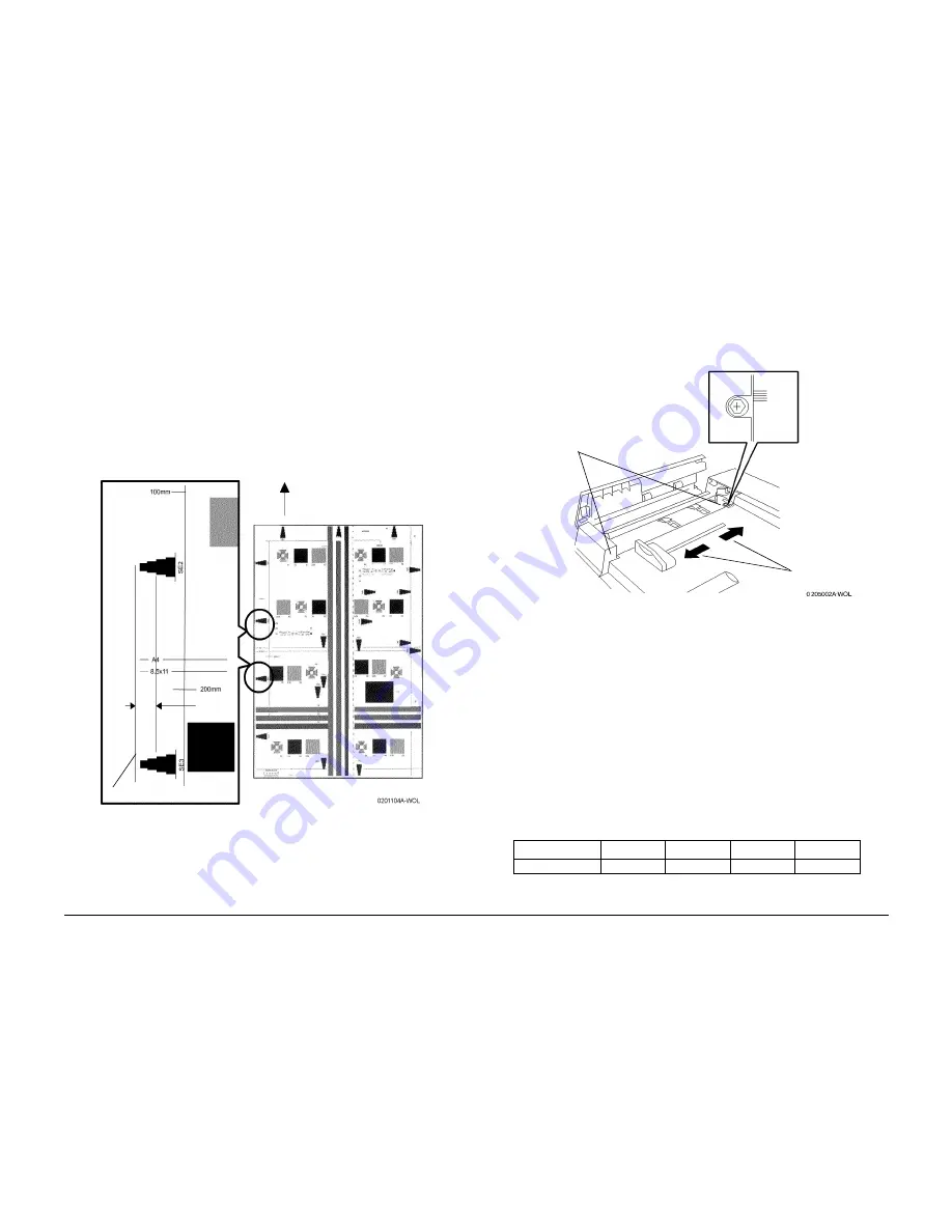
Check the copy. Verify that the distance from the side edge to the top of Step 3 on the
SE2 and SE3 scales is 10.0mm
±
3. (Figure 1)
Figure 1 ADF Side Registration Check
Adjustment
1.
Adjust by moving the Entrance Tray Assembly to either the front or the rear, as needed.
(Figure 2)
a.
If the results are less than nominal, move the tray toward the front.
b.
If the results are greater than nominal, move the tray toward the rear.
Figure 2 Adjusting Side Registration
2.
Perform the check again, and repeat the adjustment as required.
3.
Perform a fine adjustment as follows:
a.
Enter Diagnostic Mode (IIT) (GP 19).
b.
Enter Systemdata R/W and press the Select button.
c.
Enter Chain 715 and Link 7 and confirm the present values.
4.
Change the values as required, based on the measurement results. When the measure-
ment is greater than nominal, reduce the value; when the measurement is less than nom-
inal, increase the value. Change the values as follows:
NOTE: To enter a letter hexadecimal value, press the asterisk key prior to entering each letter
value, then press the appropriate numerical key as follows: A=1, B=2, C=3, D=4, E=5,
F=6
a.
Enter the new value and press Start.
b.
Press the Select button to verify the value has changed.
5.
Perform the check again.
10.0mm
±
3
Edge of copy
Paper Feed
Direction
Table 1
Minimum
Initial
Maximum
Remarks
Settings Range
0
47h
FFh
0.04mm/Step
1
Loosen the
screws (2)
2
Move the tray
3
Tighten the
screws (2)
Summary of Contents for Phaser 790
Page 4: ...10 00 ii Phaser 790 DocuColor 2006 Initial Issue Introduction...
Page 10: ...10 00 1 2 Phaser 790 DocuColor 2006 Initial Issue Service Call Procedures...
Page 46: ...10 00 2 32 Phaser 790 DocuColor 2006 002 702 Initial Issue Status Indicator RAPs...
Page 80: ...10 00 2 66 Phaser 790 DocuColor 2006 005 704 Initial Issue Status Indicator RAPs...
Page 130: ...10 00 2 116 Phaser 790 DocuColor 2006 007 713 Initial Issue Status Indicator RAPs...
Page 150: ...10 00 2 136 Phaser 790 DocuColor 2006 008 707 Initial Issue Status Indicator RAPs...
Page 180: ...10 00 2 166 Phaser 790 DocuColor 2006 009 704 Initial Issue Status Indicator RAPs...
Page 193: ...10 00 2 179 Phaser 790 DocuColor 2006 010 700 Status Indicator RAPs Initial Issue...
Page 204: ...10 00 2 190 Phaser 790 DocuColor 2006 010 705 Initial Issue Status Indicator RAPs...
Page 220: ...10 00 2 206 Phaser 790 DocuColor 2006 011 706 Initial Issue Status Indicator RAPs...
Page 226: ...10 00 2 212 Phaser 790 DocuColor 2006 016 370 Initial Issue Status Indicator RAPs...
Page 234: ...10 00 3 2 Phaser 790 DocuColor 2006 Initial Issue Image Quality...
Page 245: ...10 00 3 13 Phaser 790 DocuColor 2006 IQ8 Image Quality Initial Issue...
Page 254: ...10 00 3 22 Phaser 790 DocuColor 2006 IQ18 Initial Issue Image Quality...
Page 258: ...10 00 4 4 Phaser 790 DocuColor 2006 Initial Issue Repairs and Adjustments...
Page 268: ...10 00 4 14 Phaser 790 DocuColor 2006 REP 1 13 Initial Issue Repairs and Adjustments...
Page 276: ...10 00 4 22 Phaser 790 DocuColor 2006 REP 4 9 REP 4 10 Initial Issue Repairs and Adjustments...
Page 290: ...10 00 4 36 Phaser 790 DocuColor 2006 REP 5 10 Initial Issue Repairs and Adjustments...
Page 312: ...10 00 4 58 Phaser 790 DocuColor 2006 REP 7 8 Initial Issue Repairs and Adjustments...
Page 366: ...10 00 4 112 Phaser 790 DocuColor 2006 REP 9 22 REP 9 23 Initial Issue Repairs and Adjustments...
Page 382: ...10 00 4 128 Phaser 790 DocuColor 2006 REP 10 19 Initial Issue Repairs and Adjustments...
Page 420: ...10 00 4 166 Phaser 790 DocuColor 2006 ADJ 11 1 Initial Issue Repairs and Adjustments...
Page 512: ...03 01 6 2 Phaser 790 DocuColor 2006 General Procedures and Information...
Page 534: ...03 01 6 24 Phaser 790 DocuColor 2006 GP 23 General Procedures and Information...
Page 546: ...03 01 6 36 Phaser 790 DocuColor 2006 General Procedures and Information...
Page 548: ...10 00 7 2 Phaser 790 DocuColor 2006 Initial Issue Wiring Data...
Page 586: ...10 00 7 40 Phaser 790 DocuColor 2006 Initial Issue Wiring Data BSD 1 1 Figure 1 Main Power On...
Page 592: ...10 00 7 46 Phaser 790 DocuColor 2006 Initial Issue Wiring Data BSD 2 1 Figure 1 Control Panel...
Page 607: ...10 00 7 61 Phaser 790 DocuColor 2006 Wiring Data Initial Issue BSD 5 4 Figure 1 Document Exit...
Page 612: ...10 00 7 66 Phaser 790 DocuColor 2006 Initial Issue Wiring Data BSD 6 5 Figure 1 Image Input...
Page 627: ...10 00 7 81 Phaser 790 DocuColor 2006 Wiring Data Initial Issue BSD 8 6 Figure 1 Registration...
Page 641: ...10 00 7 95 Phaser 790 DocuColor 2006 Wiring Data Initial Issue BSD 10 1 Figure 1 Fusing...


