RS-422
Connections
77
RS-485
Connections
78
A
A
P
P
P
P
E
E
N
N
D
D
I
I
X
X
C
C
:
:
R
R
S
S
-
-
4
4
8
8
5
5
C
C
O
O
N
N
N
N
E
E
C
C
T
T
I
I
O
O
N
N
S
S
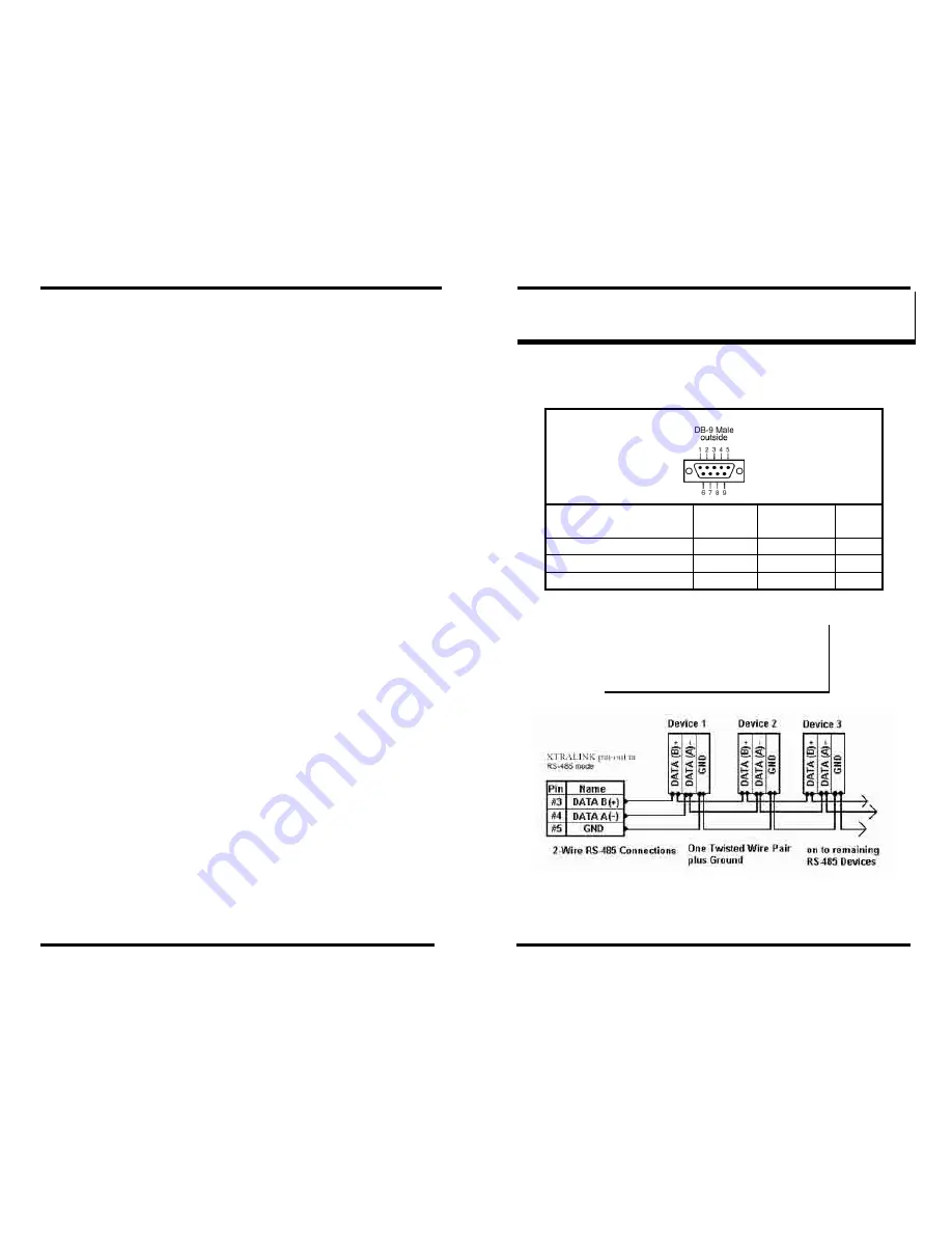
XTRALINK IP DB-9 Pin-out in RS-485 Mode
RS-485
Signal Name
Direction RS-485 DB9M
Pin
Data B (+)
In/Out
DATA B (+)
3
Data A (
−
)
In/Out
DATA A (
−
) 4
Signal Ground
--- GND
5
Figure 71. DB-9 Pin-out in RS-485 Mode
N
N
o
o
t
t
e
e
:
:
Some RS-485 devices are marked opposite the RS-485 standard,
which defines the Data B line as positive relative to Data A during a
Mark state before enabling the transmitter, and after transmitting
before tri-stating. If an RS-485 device does not XTRALINK IP
IPRS23202 Managerond, try swapping the Data B and Data A lines.
Figure 72. 2-wire RS-485 Connection


