


Manual 37259C
SPM-D11 - Synchronizing Unit
© Woodward
Page 69/79
Appendix B.
List of Parameters
Product number
P/N _____________________________ Rev _______________________________
Version SPM-D11 _____________________________________________________________
Project _____________________________________________________________________
Serial number
S/N _______________
Date
______________________________
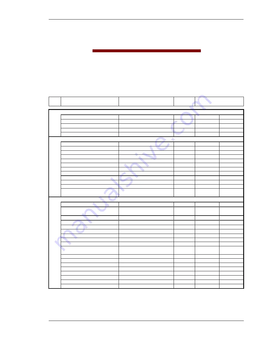
Option
Parameter
100/400V; 1/5 A
Adjustment range
Standard
setting
Customer settings
CONFIGURE GENERAL PARAMETERS
SPRACHE/LANGUAGE
german/english english
G
E
G
E
Software version
6.1xx
Enter code
0000 to 9.999
XXXX
Password
Protection
ON/OFF OFF
on
off
on
off
Direct para.
YES/NO NO
Y
N
Y
N
CONFIGURE BASIC SETTINGS
Rated Frequency
fn
48.0 to 62.0 Hz
50.0 Hz
Generator freq.
Set point
48.0 to 62.0 Hz
50.0 Hz
Gen. voltage
secondary
[1] 50 to 125 V, [4] 50 to 440 V
400 V
Mains voltage
secondary
[1] 50 to 125 V, [4] 50 to 440 V
400 V
Gen. voltage
primary
0.1 to 65.0 kV
0.4 kV
Mains voltage
primary
0.1 to 65.0 kV
0.4 kV
Rated voltage
Vn
[1] 50 to 125 V, [4] 70 to 420 V
400 V
Gen. voltage
Set point
[1] 50 to 125 V, [4] 50 to 440 V
400 V
Current transf.
Generator
10 to 9,999/x A
1000/x A
Connection type
Gen.
1W/1W2 1W2
1W
1W2
1W
1W2
Angle adjustment Gen. Curr
-180° to 180°
000
Rated power
Gen.
[1] 100 to 9,999 kW
[4] 5 to 9,999 kW
100 kW
CONFIGURE CONTROLLER
Automatic idle -
Running
ON/OFF OFF
on
off
on
off
Terminal 6
Release control/Set point power
Release con-
trol
RC
SP
RC
SP
f control type
ANALOG/PWM ANALOG
Freq. controller
ON/OFF ON
on
off
on
off
Freq. controllerIsol. oper.
ON/OFF AUS
on
off
on
off
Freq. controller
Ramp.
0.1 to 99.9 Hz/s
5.0 Hz/s
Freq. controller Dead band
0.02 to 1.00 Hz
0.10 Hz
Freq. controllerTime pulse >
10 to 250 ms
80 ms
Freq. controller
Gain Kp
0.1 to 99.9
15.0
f control output
see table
+/-20 mA
(+/-10 V)
f control output Level PWM
3.0 to 10.0 V
10.0 V
PWM-signal Logic
positive/negative positive
f control output Init.state
0 to 100 %
50 %
f control output
(max.)
0 to 100 %
100 %
f control output
(min.)
0 to 100 %
0 %
Freq. controller
Gain Kp
1 to 240
15
Freq. controller
Reset Tn
0.0 to 60.0 s
2.5 s
Freq. controller Derivat.Tv
0.00 to 6.00 s
0.00 s


