background image

Setup & Operation

Edging

2

2-29

HDdoc012020

Setup & Operation

9.

Lower the toe boards, if they were used. Use the hydraulic levers to release the clamp and engage the log
turner. Turn the log 90 or 180 degrees. Make sure the flat on the log is placed flat against side supports if
turned 90 degrees. Make sure it is placed on bed rails if turned 180 degrees. If the log was turned 90 degrees
and you are using toe boards to compensate for taper in the log, raise the front or rear toe board again on the
second side of the log until the heart is parallel with the bed.

10.

Repeat the steps used to cut the first side of the log until the log is square. Cut boards from the remaining cant
by adjusting the blade height for the thickness of boards that you want.

Example:

 Remember that the blade cuts a 1/16 - 1/8" (1.6-3.2 mm) wide kerf. If you want 1" (25.4 mm) thick

boards, lower the carriage 1 1/16 - 1 1/8" (27-28.6 mm) for each board.

2.17 Edging

The following steps guide you through edging boards on the Wood-Mizer sawmill.

1.

Raise the side supports to 1/2 the height of the flitches, or the boards that need to be edged.

2.

Stack the flitches on edge against the side supports.

3.

Clamp the flitches against the side supports halfway up the flitch height. (Wider flitches should be placed to the
clamp side. When they are edged, flip them over to edge the second side without disturbing the other flitches
or without having to pull them from the middle of the stack).

4.

Adjust the blade height to edge a few of the widest boards.

5.

Loosen the clamp and turn the edged boards over to edge the other side.

6.

Repeat steps 2-4.

7.

Loosen the clamp and remove the boards that have good clean edges on both sides. Clamp the remaining
flitches and repeat steps 2-5.

2.18 Blade Height Scale

See Figure 2-22. 

The blade height scale is attached to the carriage head frame. It includes:

a blade height indicator

an inch scale

a quarter scale

Summary of Contents for LT40 Series

Page 1: ......

Page 2: ......

Page 3: ...aintenance Manual LT40 Series DH rev F1 00 Safety is our 1 concern Read and understand all safety information and instructions before oper ating setting up or maintaining this machine Form 604 This is the original language for the manual ...

Page 4: ... A Under 1300 kg B 1301 1800 kg C 1801 2200 kg D 2201 3000kg X Stationary Product No 1 LT10 15 2 LT20 Series 4 LT40 Series 7 LT70 Series Length of the Trailer 20 20 6 m 24 24 7 m 35 35 11 m Number of axles on the trailer Year of Manufacture N 2015 P 2016 R 2017 S 2018 T 2019 State of Manufacture N Indiana P Poland Month of Manufacture A January B February C March etc Revision Level Sequence Number...

Page 5: ... a description of the model number When you pick up your mill you will receive a customer number Both the VIN and your customer number expedite our service to you Please write these numbers below so you have quick easy access to them MODEL NUMBER DESCRIPTION Customer No Model No V I N Revision LT40DH Basic Sawmill I D G28 Configuration Engine Motor ...

Page 6: ...28 1 18 LT40 Series DH7 Hydraulic Schematic 1 30 1 19 LT40 Series DH Hydraulic Components 1 32 1 20 LT40 Series DH Hydraulic Hoses 1 33 SECTION 2 SETUP OPERATION 2 1 2 1 Sawmill Setup 2 1 2 2 Stationary Sawmill Setup 2 4 2 3 Portable Sawmill Setup 2 8 2 4 Middle Track Cover 2 11 2 5 Replacing The Blade 2 12 2 6 Tensioning The Blade 2 12 2 7 Tracking The Blade 2 13 2 8 Starting The Engine or Motor ...

Page 7: ...9 SECTION 4 TROUBLESHOOTING GUIDE 4 1 4 1 Sawing Problems 4 1 4 2 Electrical Problems 4 3 4 3 Power Feed Problems 4 4 4 4 Power Feed Circuit Troubleshooting 4 6 4 5 Hydraulic Problems 4 7 4 6 Engine Motor and Drive Pulleys Alignment 4 9 4 7 Power Feed Preliminary Test 4 10 4 8 Power Feed Mechanical Test 4 10 4 9 Fuse Terminal Extension Stud 4 10 4 10 Circuit Breaker Operation 4 11 SECTION 5 SAWMIL...

Page 8: ...uide Spacing 5 20 5 13 Horizontal Tilt Adjustment 5 21 5 14 Blade Guide Block Adjustment 5 22 5 15 Horizontal Adjustment of Side Supports 5 23 5 16 Vertical Adjustment of Side Supports 5 24 5 17 Clamp Stop Stop Bolt Adjustment 5 25 5 18 Saw Head Tilt 5 26 5 19 Blade Height Scale Adjustment 5 27 5 20 Board Return Bracket 5 28 ...

Page 9: ...operating this equipment Also read any additional manufac turer s manuals and observe any applicable safety instructions including dangers warnings and cautions Always be sure that all safety decals are clean and readable Replace all damaged safety decals to prevent personal injury or damage to the equipment Contact your local distributor or call your Customer Service Rep resentative to order more...

Page 10: ...lure to do so will result in serious injury WARNING Always wear gloves and eye protection when handling bandsaw blades Changing blades is safest when done by one person Keep all other persons away from area when coiling carrying or changing a blade Failure to do so may result in serious injury WARNING Do not spin the blade wheels by hand Spinning the blade wheels by hand may result in serious inju...

Page 11: ...p over resulting in serious personal injury CAUTION Changes in temperature could cause increased pressure in the blade tensioner and loss of fluid from the gauge Release the blade tension when the mill is not in use to avoid damage to the tensioner 1 3 Sawmill Operation IMPORTANT The sawmill is intended for sawing wood only See Section 1 8 for log size capacities of the machine The sawmill must no...

Page 12: ...esult in serious injury or death WARNING Always leave loading arm halfway up while log is on sawmill bed Failure to do so may result in serious injury or death WARNING Use ONLY water with the water lube accessory Never use flam mable fuels or liquids If these types of liquids are necessary to clean the blade remove it and clean with a rag Failure to do so may result in serious injury or death CAUT...

Page 13: ...amage to the saw head and or blade guide arm CAUTION Never clean the blade or the blade wheels with a brush or a scraper during sawmill operation CAUTION Before installation of the blade inspect it for damage and cracks Use only properly sharpened blades Always handle the blade with extreme caution Use suitable carrier equipment for transporting the blades CAUTION Always wear gloves when handling ...

Page 14: ...saw head Check the pad spacing at the top and bottom ends of the mast only Pads adjusted too tight will cause premature up down motor failure CAUTION It is important that the lower stop bolts are properly adjusted to secure the carriage on the track rail Failure to properly adjust the stop bolts can cause saw head damage especially during mill transportation CAUTION Pressure should not exceed 2000...

Page 15: ...s manual should operate the sawmill The sawmill is not intended for use by or around children IMPORTANT It is always the owner s responsibility to comply with all applicable federal state and local laws rules and regulations regard ing the ownership and operation of your Wood Mizer sawmill All Wood Mizer sawmill owners are encouraged to become thoroughly familiar with these applicable laws and com...

Page 16: ...Failure to do so may result in serious injury WARNING Always wear eye ear respiration and foot protection when operating or servicing the sawmill Keep sawmill And Area Around sawmill Clean DANGER Maintain a clean and clear path for all necessary movement around the sawmill and lumber stacking areas Failure to do so will result in serious injury Dispose Of Sawing By Products Properly IMPORTANT Alwa...

Page 17: ... off the blade motor before changing the blade Failure to do so will result in serious injury DANGER Motor components can become very hot during operation Avoid contact with any part of a hot motor Contact with hot motor com ponents can cause serious burns Therefore never touch or perform service functions on a hot motor Allow the motor to cool sufficiently before beginning any service function DA...

Page 18: ...sed and securely fastened during sawmill operation WARNING Consider all electrical circuits energized and dangerous WARNING Disconnect and lock out power supply before servicing the sawmill Failure to do so may result in serious injury WARNING Never assume or take the word of another person that the power is off check it out and lock it out WARNING Do not wear rings watches or other jewelry while ...

Page 19: ...en the blade housing cover CAUTION The sawmill s work stand should be equipped with a 4 kg or bigger dry powder extinguisher Keep Safety Labels In Good Condition IMPORTANT Always be sure that all safety decals are clean and readable Replace all damaged safety decals to prevent personal injury or damage to the equipment Contact your local distributor or call your Customer Service Representative to ...

Page 20: ...E 1 1 Decal View W M No Description 096317 CAUTION Read thoroughly the manual before operating the machine Observe all safety instructions and rules when operating the sawmill 099220 CAUTION Close all guards and covers before starting the machine 099219 Blade tension Turning the bolt clockwise will increase the blade tension and turning the bolt counterclockwise will decrease the tension 099220 09...

Page 21: ...l Information HDdoc012020 1 13 1 099223 Blade tension See manual 099221 CAUTION Keep all persons a safe distance away from work area when operating the machine 098176 CAUTION Keep away from debarker blade 099222 CAUTION Sawdust outlet Protect eyes TABLE 1 1 099223 099221 098176 ...

Page 22: ... 086099 CAUTION Keep away hot parts 096321 Blade movement direction 512235 Clean the chain of sawdust every 50 hours of operation or once a week 512157 Lubricate the chain every 50 hours of operation or once a week S12004G CAUTION Always wear safety goggles when operating the sawmill TABLE 1 1 099542 086099 512235 50h 512157 OIL 50h ...

Page 23: ... Information HDdoc012020 1 15 1 S12005G CAUTION Always wear protective ear muffs when operating the sawmill 501465 CAUTION Always wear safety boots when operating the sawmill 501467 Lubrication Point P11789 Aligning the blade on the wheels P85070 CE safety certification TABLE 1 1 ...

Page 24: ...eral Information Keep Safety Labels In Good Condition 1 1 16 HDdoc012020 Safety General Information 099401 Russian safety certification S20097B 3300 RPM Motor rotation direction TABLE 1 1 099401 S20097B 3300 RPM ...

Page 25: ...x920 085753 Alternator Belt D33 6PK1080 088181 Blade Pulley Belts B57 1 1 To insure proper blade tracking use Goodyear Dayco Super II or Browning belts only P04185 TABLE 1 2 Softwood Medium Hardwood Frozen Timber or Dense Hardwood 5 15HP Gas B275IH1030 B275IH741030 B375IH929 B375IH929 1 1 TRU SHARP F blades use a 9 29 profile 9 hook angle and 29 back angle and are designed to cut frozen and or ext...

Page 26: ...7 4 8 m LT40 M DH 36 91 5 cm 20 6 1 m LT40 S DH with Optional 6 Bed Extension 2 36 91 5 cm 22 8 6 9 m LT40 M DH with Optional 6 Bed Extension 2 36 91 5 cm 27 8 2 m LT40 S DH with Optional 12 Bed Extension 2 2 Logs over 4400 lbs must be distributed so that neither the basic mill or extension is loaded beyond the 4400 lb maximum weight rating Loading logs heavier than 4400 lbs 1996 Kg on a mill equi...

Page 27: ...2V 1800 RPM 600W 024169 Up Down Motor Leeson USA 12V 1800 RPM 600W 015174 Blade Guide Arm Motor Motor Products Owosso USA 12V 60 RPM 17W P09698 1 Hydraulic Pump Motor Iskra 12V 2400 RPM 1320W 038683 TABLE 1 7 Sawmill Noise Level LEX8 LT40 sawmill equipped with Diesel engine 87 7 dB A TABLE 1 8 1 The noise level measurement was taken in accordance with PN EN ISO 3746 Standard The noise exposure lev...

Page 28: ...n square value of weighted acceleration to which the whole operator s body is subjected does not exceed 0 5 m s2 Airflow 1200 m3 h 3937ft3 h Inlet diameter 100 mm 5 9 Motor power 1 5 kW Number of sacks 1 pcs Sack capacity 0 25 m3 8 8 ft 3 Weight 110 kg 242 5 lb Pressure drop 1 5 kPa 0 22 psi 1 1 The pressure drop between the inlet of the capture device and the connection to the CADES should be max...

Page 29: ... from fender to fender With Operating Position with Loading Arms Height 3 3 Height from ground to mast Placing head in maximum position will add to total height Weight 4 4 Weight based on basic gas unit Other power options may change total weight Options such as Re mote Operation and Debarker will add to total weight Weight w Trailer LT40 S DH 21 11 6 7 m 6 6 2 m 8 2 2 5 m 7 8 2 4 m 3291 lbs 1481 ...

Page 30: ... 11 The load capacity of the chains is listed below 1 14 Hydraulic System See Table 1 12 The specifications of the hydraulic system are shown below FIG 1 2 Load Capacity According to ISO Nr 08A 1 Power Feed Chain 1780N Up Down Chain 1780N TABLE 1 11 Hydraulic Pump M 300 0230 Monarch Pressure Rating 17 25MPa 2500 PSI Max Pressure 19MPa 2750 PSI TABLE 1 12 ...

Page 31: ...y Outer Blade Guide Arm Blade Guide Rollers Blade Tensioner Clutch Brake Handle Control Box Hydraulic Control Box Trailer Hitch W Optional Trailer Pivot End Rail Hydraulic Log Loader Optional Trailer Axle Adjustable Outrigger Leg W Optional Trailer Side Support Hydraulic Toe Board Hydraulic Log Clamp Hydraulic Log Turner HD0058 Cutting Head Control Box Engine Drive Assembly Blade Tensioner ...

Page 32: ...ard Loader Arm See Figure 1 3 FIG 1 3 HYDRAULIC SCHEMATIC HD0138 H13 H13 H8 H5 H16 H11 H13 H15 H14 H1 H2 H7 H6 H12 H3 H9 CLAMP IN OUT CLAMP UP DOWN CLAMP UP DOWN CLAMP IN OUT TURNER LOADER ARM RELIEF VALVE SETTING 2000 PSI RELIEF VALVE SETTING 2250 PSI TOEBOARD TOEBOARD FRONT TOEBOARD REAR TOEBOARD TURNER SIDE SUPPORT LOADER ARM LOADER ARM H4 H17 H10 3 8 3 x 7 7 8 1 x 10 1 x 6 1 x 6 2 x 6 2 1 2 x ...

Page 33: ...de Support Front Toe Board Rear Toe Board Log Loader Shown with handles down FIG 1 4 HYDRAULIC LAYOUT DIAGRAM C1 C2 C3 H2 H7 H6 H9 H10 H11 H12 H13 H14 H15 H16 H17 H8 H5 H4 H3 C4 C5 C6 C7 C8 V1 M1 P1 F1 V2 V3 V4 V5 H1 Shown with handles down Clamp In Out Clamp Up Down Turner Side Supports Front Toe Board Rear Toe Board Log Loader HD0137 ...

Page 34: ...d Rear Toe Board Loader Arm FIG 1 5 HYDRAULIC SCHEMATIC HD0139C H14 H14 H9 H6 H17 H12 H13 H16 H15 H2 H1 H3 H8 H7 H13 H4 H10 CLAMP IN OUT CLAMP UP DOWN CLAMP UP DOWN CLAMP IN OUT TURNER LOADER ARM RELIEF VALVE SETTING 2000 PSI RELIEF VALVE SETTING 2250 PSI TOEBOARD TOEBOARD FRONT TOEBOARD REAR TOEBOARD TURNER SIDE SUPPORT LOADER ARM LOADER ARM H5 H18 H11 3 8 3 x 7 7 8 1 x 10 1 x 6 1 x 6 2 x 6 2 1 2...

Page 35: ...ont Toe Board Rear Toe Board Log Loader Shown with handles down Crossflow Hose 3 8 FIG 1 6 HYDRAULIC LAYOUT DIAGRAM C1 C2 C3 H3 H8 H7 H10 H11 H12 H13 H14 H15 H16 H17 H18 H9 H6 H5 H4 C4 C5 C6 C7 C8 V1 M1 P1 F1 M2 P2 V2 V3 V4 V5 H2 H1 Shown with handles down Clamp In Out Clamp Up Down Turner Side Supports Front Toe Board Rear Toe Board Log Loader HD0136B Crossflow Hose 3 8 ...

Page 36: ...t Clamp Up Down Turner Side Support Toeboard Loader Arms Toeboard Front Toeboard Rear Front Clamp Up Down Front Clamp In Out Rear Clamp In Out Rear Clamp Up Down P1 H1 C1 C2 C3 C4 C5 C6 C7 C8 C9 C10 C9 C10 H2 H6 H7 H8 H9 H17 H18 H3 V2 V3 H4 H5 H10 H11 H12 H13 H13 V4 V5 H13 H14 H15 V1 V6 H27 H19 H20 H21 H22 H23 H24 H25 H26 Toeboard Rear Clamp In Out Rear Clamp Up Down Front Clamp In Out Front Clamp...

Page 37: ...afety General Information HDdoc012020 1 29 1 Relief valve setting 2000 2250 PSI Clamp In Out Clamp Up Down Turner Side Support Toe Board Toe Board Front Toe Board Rear Loader Arm Loader Arms Front Clamp Up Down Front Clamp In Out Rear Clamp Up Down Rear Clamp In Out ...

Page 38: ...de Support Toeboard Toeboard Loader Arms Turner Toeboard Front Toeboard Rear Loader Arm Clamp Up Down I Clamp In Out I II III P1 H1 C1 C2 C3 C4 C5 C6 C7 C8 C10 C9 C9 C9 H2 H6 H7 H8 H9 H17 H18 H3 V2 V3 H4 H5 H10 H11 H12 H13 H13 V4 V5 H13 H14 H15 V1 C10 C10 Clamp Up Down II Clamp Up Down III Clamp Up Down I Clamp Up Down II Clamp Up Down III V6 Clamp In Out I Clamp In Out II Clamp In Out III H27 H35...

Page 39: ...lic Schematic Safety General Information HDdoc012020 1 31 1 Relief valve setting 2000 2250 PSI Clamp In Out Clamp Up Down Turner Side Support Toe Board Toe Board Front Toe Board Rear Loader Arm Loader Arms Clamp Up Down I II III Clamp In Out I II III ...

Page 40: ... X 203mm Stroke C4 CJ S270 16 5 0 28 152 088678 Hyd Cylinder 50mm Bore X 152mm Stroke C5 C6 CJ S170 16 4 0 25 152 088681 Hyd Cylinder 40mm Bore x 152mm Stroke C7 C8 CJ S95 16 70 32 203 088680 Hyd Cylinder 70mm Bore X 203mm Stroke C9 CJ7F 16 40 2 2 UE2 40W 091346 Hydraulic Cylinder C10 SJ2F 16 40 2 2 80 093880 Hydraulic Cylinder P1 P2 M300 0230 P12701 Hydraulic Pump With Motor V1 HDS10 6 6 015260 V...

Page 41: ...S 087790 3 83m 151 1 4 Front Toe Board Base LT40M 087776 H7 Pink 4 2m 166 3 8 Side Support Cylinder Base LT40S 087791 4 77m 188 3 8 Side Support Cylinder Base LT40M 087777 H8 Plain 4 2m 166 3 8 Side Support Cylinder Top LT40S 087791 4 77m 188 3 8 Side Support Cylinder Top LT40M 087777 H9 White 3 68m 145 3 8 Clamp Cylinder Top LT40S 087792 4m 157 3 8 Clamp Cylinder Top LT40M 087778 H10 Dark Orange ...

Page 42: ... DH5 094780 H24 ORANGE 236 3 8 REAR LOG CLAMP IN OUT CYLINDER TOP A DH5 094780 H25 RED 220 3 8 REAR LOG CLAMP UP DOWN CYLINDER BOTTOM A DH5 094781 H26 BLUE 220 3 8 REAR LOG CLAMP UP DOWN CYLINDER TOP A DH5 094781 H27 PLAIN 15 3 8 VALVE TO OIL FLOW CONTROL VALVE A DH5 094782 H28 PLAIN 21 3 8 HYDRAULIC PUMP W MOTOR TO OIL FLOW CONTROL VALVE A DH5 087775 H29 RED 1 50 1 4 FIRST CLAMP UP DOWN CYLINDER ...

Page 43: ...ty General Information HDdoc012020 1 35 1 H40 WHITE 2 50 1 4 FIRST SECOND CLAMP IN OUT CYLINDER TOP AH7 095216 H41 ORANGE 1 20 1 4 FIRST SECOND CLAMP IN OUT CYLINDER BOTTOM AH7 095217 H42 WHITE 1 20 1 4 FIRST SECOND CLAMP IN OUT CYLINDER TOP AH7 095217 TABLE 1 14 ...

Page 44: ...te foundation or pads rated to support 31 T m2 at each sawmill foot position and 16mm anchored bolts are recommended It is not allowed to use the sawmill indoor When using this sawmill type outdoor it is allowed to work without sawdust collection system connected We recommend to setup sawmill in the way that operator position be down the wind It will separate the operator from sawdust and engine e...

Page 45: ... button located on the control box to stop the blade and the track feed motor Turn the emergency stop clockwise to release the stop The sawmill not restart until the emergency stop is not released WARNING In case of a blade or drive belt brake wait until all rotating parts are completely stop Failure to do so may result in serious injury ...

Page 46: ... picture below The sawmill can be lifted using a forklift a winch or a crane The belts and the lifting equipment must be rated for at least 3000kg 6600 lb WARNING When lifting sawmill use extreme caution and keep all persons at a safe distance Failure to do so may result in serious injury or death sm0378 ...

Page 47: ...31 T m2 at each sawmill foot position NOTE Make sure the unit is level before securing It IS possible to twist the mill frame by jacking one foot higher than the others Level the sawmill by adjusting the feet to raise or lower each end of the sawmill Adjust all feet evenly to avoid twisting the mill frame by jacking one feet higher than the others WARNING Securely fasten the feet of a stationary s...

Page 48: ...Setup Operation Stationary Sawmill Setup 2 2 5 HDdoc012020 Setup Operation See Figure 2 2 FIG 2 2 ...

Page 49: ...25 2790 775 LT20 S Stationary Metric Dimensions LT20 M Stationary Metric Dimensions All dimensions in millimetres 853 300 1453 2082 4 1742 6 882 1592 8 1500 9 88 680 2 326 680 2 170 LT40S Stationary Metric Dimensions LT40M Stationary Metric Dimensions LT40S Stationary Metric Dimensions LT40M Stationary Metric Dimensions All dimensions in millimetres ...

Page 50: ...om the carriage rest pin Remove the locking pin and swing the rest pin down below bed level 3 Use the carriage forward reverse switch left side of control box to move the cutting head toward the front end of the mill The hydraulic control levers become operational when the contacts at the bottom of the carriage touch the power strip on the frame tube The hydraulic control levers will only work whe...

Page 51: ...ng the sawmill frame when operating a sawmill with adjustable outriggers Failure to do so may result in serious injury or death The adjustable outriggers are intended to support the saw frame with assistance from the trailer 1 Pull the hand brake to fix the machine 2 Unhitch the mill from the vehicle 3 Lower and set the front outriggers Manually pull the locking pin out of the outrigger hole When ...

Page 52: ...Operation CAUTION If setup sawmill on a boggy terrain such as deep mud or sand place the board or metal plate under each outrigger leg to prevent it from sink ing See Figure 2 8 FIG 2 8 OUTRIGGER ADJUSTMENT Adjustment Bolt Outrigger Leg Travel Lock Pin Locking Pin ...

Page 53: ...lt in serious injury 6 Remove the fenders by lifting them out of the slots CAUTION To prevent fender damage remove fenders before operating sawmill or loading logs 7 Use the carriage forward reverse switch left side of control box to move the cutting head toward the front end of the mill Lower and set the remaining rear outriggers 8 Level the sawmill by adjusting the outriggers to raise or lower e...

Page 54: ... 3 Soak the felt wiper with Dexron III transmission fluid 10W30 motor oil or 3 in 1 turbine oil 4 Install the middle track cover so it fits against the rail and secure with two thumb screws See Figure 2 10 CAUTION Install the track cover so that it lightly touches the track rail If the wiper presses too firmly against the rail it can cause the power feed to bind FIG 2 10 Install the track cover an...

Page 55: ...g a blade make sure the teeth are pointing the correct direction The teeth should be pointing toward the operator side of the mill when you are looking at the blade below the blade guides Install the blade so it is lying around the wheels Position 1 1 4 wide blades on the wheels so the gullet is 1 8 3 0 mm out from the edge of the wheel Posi tion 1 1 2 wide blades on the wheels so the gullet is 3 ...

Page 56: ... shift Tension the blade again before starting the motor 2 7 Tracking The Blade 1 Make sure the middle blade housing cover is closed and all persons are clear of the open side of the saw head 2 Start the engine or motor 3 Pull lightly on the clutch handle rotating the blade until the blade positions itself on the wheels WARNING Do not spin the blade wheels by hand Spinning the blade wheels by hand...

Page 57: ...d before operating or towing the sawmill Failure to do so may result in serious injury Be sure the blade housing and pulley covers are in place and secure Use the safety retainer pin and cable to fasten blade housing covers IMPORTANT After aligning the blade on the wheels always double check the blade guide spacing and loca tion See Section 5 for more information 2 8 Starting The Engine or Motor S...

Page 58: ...wmill Failure to do so may result in serious injury WARNING Be sure the power feed switch is in the neutral position before turning the key switch to the on 1 or accessory 3 position This prevents accidental carriage movement which may cause serious injury or death CAUTION If at any time you need to immediately stop the blade motor press the emergency stop button located on the control box ...

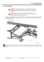
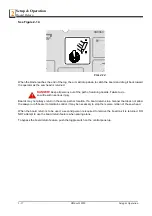
Page 59: ... and intended to assist in the removal of boards only Standing on the table may result in serious injury Sawmills can be equipped with a board return system This system consists of an arm on the saw head controlled by a toggle switch on the control panel A board return table is also provided to catch the board as it is removed from the log To activate the board return turn the key switch to the ac...

Page 60: ...ll result in serious injury Boards may not always return in the same path or location If a board returns in a manner that does not allow the sawyer or off bearer to maintain control it may be necessary to stop the reverse motion of the saw head When the board return is to be used a second person is required to remove the board as it is returned DO NOT attempt to use the board return feature when s...

Page 61: ...c units have six control levers to load clamp turn and level logs DH5 and DH7 hydraulic units have four additional levers for controlling the Pull Down clamps In sawmills equipped with DH5 hydraulic system individual Pull Down clamps are controlled with separate levers In sawmills with DH7 hydraulic system in out movement of individual clamps is controlled with the same lever and up down movement ...

Page 62: ...R Keep all persons out of the path of moving equipment and logs when operating sawmill or loading and turning logs Failure to do so will result in serious injury FIG 2 16 FIG 2 17 A DH3 Front Clamp Up Down HD0185 Front Clamp In Out Rear Clamp Up Down Rear Clamp In Out Front Clamp In Out Rear Clamp In Out Front Clamp Up Down Rear Clamp Up Down A DH3 Clamp I Up Down Clamp II Up Down Clamp I II III I...

Page 63: ...lowered but before the side supports begin to lower This stops the log being loaded from damaging the turner and or falling off the side of the sawmill 6 When raising the turner lever the side supports rise first After reaching a fully vertical position the turner arm will engage and start to rise 7 Manually lower the log loader so the legs rest on the ground CAUTION Be careful when manually lower...

Page 64: ...aring the log This will stop the log from rolling off the side of the mill WARNING Always leave loading arm halfway up while log is on sawmill bed Failure to do so may result in serious injury or death NOTE Logs also may be loaded onto the mill with a tractor or other equipment specifically designed for that purpose 5 Raise the clamp up to prevent the log from rolling of the bed 6 Raise the clamp ...

Page 65: ... below the bed 3 When the turner arm is lowered all the way the side supports will begin to lower Back the clamp off slightly and let the side supports come down until they are positioned below the level of your first few cuts To Level A Tapered Log Use the toe board lever s to raise either end of a tapered log if desired Raise the appropriate lever to raise the front or rear toe board until the h...

Page 66: ...d the switch in position until the cutting head reaches the desired height then release The up down switch is designed to return to the neutral or off position when released If the switch remains engaged manually move the switch to the neutral or off position Repair the up down drum switch See Sec tion 4 2 CAUTION Always make sure the up down switch moves to the neutral or off position when releas...

Page 67: ...4 mm 2 Use the blade guide toggle switch on the control panel to adjust the outer blade guide as necessary Push the switch to the left to move the arm in Push the switch to the right to move the arm out See Figure 2 19 3 Use the blade guide toggle switch to readjust the outer blade guide as you are cutting in order to keep the guide within 1 2 5 cm of the log Be sure to adjust the arm back out bef...

Page 68: ... operating or towing the sawmill Failure to do so may result in serious injury Be sure the blade housing and pulley covers are in place and secure Use the safety retainer pin and cable to fasten blade housing covers Be sure the blade housing and pulley covers are in place and secure before starting the engine or motor Use the safety retainer pin and cable to fasten blade housing covers See Figure ...

Page 69: ...s forward Turn the switch clock wise to increase speed Turn it counterclockwise to reduce speed Carriage Forward and Reverse The carriage forward reverse switch controls the direction in which the carriage travels Turn the for ward reverse switch upward to move the carriage forward Turn the switch down to move the carriage back ward The middle position as shown is the neutral position The power fe...

Page 70: ... the carriage to the front of the mill by turning the carriage forward reverse switch down Always disen gage the blade before returning the carriage for the next cut IMPORTANT When using a sawmill it is very important not to switch between saw head forward backward movement until the saw head stops Failure to do so may result in serious sawmill damage 4 Make sure that the blade does not catch on t...

Page 71: ...ke sure all covers and guards are in place Start the engine Engage the clutch brake lever to start the blade spinning 4 Start the water lube if necessary to prevent sap buildup on the blade See Section 2 19 5 Feed the blade into the log slowly See Section 2 15 Once the blade completely enters the log increase the feed rate as desired Always try to cut at the fastest speed you can while keeping an ...

Page 72: ... boards lower the carriage 1 1 16 1 1 8 27 28 6 mm for each board 2 17 Edging The following steps guide you through edging boards on the Wood Mizer sawmill 1 Raise the side supports to 1 2 the height of the flitches or the boards that need to be edged 2 Stack the flitches on edge against the side supports 3 Clamp the flitches against the side supports halfway up the flitch height Wider flitches sh...

Page 73: ...nt on the inch scale Make a trim cut Return the carriage for the second cut and lower it 1 1 8 29 mm below the original measurement The extra 1 8 3 mm allows for saw kerf and shrinkage of the lumber The yellow area on the scale identifies where the blade could encounter a side support or log clamp Check that these items are below the blade level before sawing The Quarter Scale See Table 2 2 Two qu...

Page 74: ...thout having to measure on the inch scale Example You want to cut 1 25 mm 4 4 random width boards from a log Position the blade for the first cut Adjust the quarter scale so a 4 4 mark is aligned with the red line on the indicator Make a trim cut Return the carriage for the second cut Now instead of having to measure down 1 1 8 29 mm on the inch scale you can simply lower the blade so the indicato...

Page 75: ...tle will help clean the blade when cutting wood with a high sap content WARNING Use ONLY water with the water lube accessory Never use flam mable fuels or liquids If these types of liquids are necessary to clean the blade remove it and clean with a rag Failure to do so may result in serious injury or death Before removing the blade engage the clutch brake lever Let the blade spin with water runnin...

Page 76: ...sult in damage to the sawmill 3 Use the hydraulic controls to raise the log turner and loader as high as they will go Manually lift the loader and hook the loader chain to the elbow of the turner Use the hydraulic turner lever to lower the turner until the chain is tight Push the loader lever down to bring the loader arm channels up to the loader 4 Move the carriage forward to the travel position ...

Page 77: ...he carriage safety chain located at the bottom of the carriage to the bracket at the bottom of the mast See Figure 2 26 CAUTION Check to be sure the saw head safety chain is secured before towing the sawmill Failure to properly secure the saw head can result in severe machine damage Be sure the blade housing and pulley covers are in place and secure Use the safety retainer pin and cable to fasten ...

Page 78: ...020 Setup Operation 13 Place both fenders in the slots located behind the trailer tires and secure with retaining pins Raise all but the very front outrigger See the trailer operator s manual for specific information regarding hitch operation and towing the sawmill ...

Page 79: ...ocedure should be performed Be sure to refer to option and engine manuals for other maintenance procedures 3 1 Wear Life See Table 3 1 This chart lists estimated life expectancy of common replacement parts if proper maintenance and operation procedures are followed Due to the many variables which exist during sawmill operation actual part life may vary significantly This information is provided so...

Page 80: ...use them It is recommended you develop a routine schedule for replacing the blade guide blocks based on your sawing conditions and experience 3 Check the inserts are properly spaced from the bottom of the blade every 25 hours of operation As the rollers wear the gap between the blade and inserts will become larger Use the provided shim or a feeler gauge to check the inserts are adjusted 0 3 0 5 mm...

Page 81: ...ed to its lowest position 3 4 Carriage Track Wiper Scrapers 1 Clean the upper and lower track rails to remove any sawdust and sap buildup every eight hours of operation Lubricate the lower track rail by wiping it with Dexron III ATF 2 Remove sawdust from the upper cam housings Loosen the thumb screws on the upper cam housing covers and open Brush any sawdust buildup from the housings 3 Check the t...

Page 82: ...l every fifty hours of opera tion Use only contact grease supplied by Wood Mizer Remove the control panel cover Use a cotton swab to apply grease to the switch contact ends WARNING Drum switch grease contains Petroleum Hydrocarbon Lubricant Eye and skin irritant If introduced into eyes flush with water for at least 15 minutes If film or irritation persists seek medical attention Wash skin with soa...

Page 83: ...lignment 5 Make sure all safety warning decals are readable Remove sawdust and dirt Replace any damaged or unread able decals immediately Order decals from your Customer Service Representative 6 Lubricate the clutch lever bushings every 200 hours of operation or once a month Apply lithium grease to the fitting 3 8 Blade Tensioner 1 Lubricate the chrome rods of the tensioner system with a heavy dut...

Page 84: ... 7 16 wrench to remove the plug making sure to keep the plug o ring with the plug Manually extend the rear piston the front piston should remain extended Use a small funnel or cup to completely fill the block with hydraulic fluid When full place the fill plug in the fill plug hole and thread 1 2 turns Manually push the rear piston all the way in to allow excess oil and air to bleed from system thr...

Page 85: ...r when the brake is applied or a sudden change is noticed in the clutch handle position when the clutch is disengaged To access the brake strap remove the belt cover located underneath the engine Engage the clutch brake lever Loosen the two nuts on the upper brake strap bracket Slide the bracket and brake strap down until snug Retighten the bolts Replace the belt cover See Figure 3 6 FIG 3 6 200 A...

Page 86: ...Handle Loosen the drive belt turnbuckle jam nuts Turn the turnbuckle counterclockwise as viewed from the top to tighten the belt clockwise to loosen the belt See Figure 3 7 3 For Autoclutch Option Place a wrench on the flats at the top of the turnbuckle Use a second wrench to turn the bottom most jam nut clockwise as viewed from the bottom to tighten the belt counterclockwise to loosen the belt En...

Page 87: ...PM while the clutch brake handle is disengaged NOTE A properly adjusted throttle will extend the cable spring 1 4 to 3 8 6 4 9 5 mm when running and have a slight amount of slack in the cable when idling Always be sure to check the drive belt support after adjusting drive belt tension Periodically check all belts for wear Replace any damaged or worn belts as needed FIG 3 8 Hold top portion with wr...

Page 88: ... the drive belt away from the engine pulley when the clutch handle is disengaged up position See Figure 3 9 To adjust the drive belt support 1 Make sure the motor is not running Loosen the adjustment bolts 2 Position the bracket so that the prong is close to but does not touch the drive belt with the clutch handle engaged 3 Re0tighten the adjustment bolts 25 27 pound feet 34 37 newton meters FIG 3...

Page 89: ...r optional Autoclutch adjustment 1 Remove the blade from the sawmill 2 Remove the inner belt guard and pull the clutch handle down to engage the drive belts 3 Hold a straight edge between the bottom and top pivot centers and measure the distance to the middle pivot 4 Adjust the clutch handle turnbuckle until the center of the middle pivot is 7 16 from the straight edge See Figure 3 10 FIG 3 10 3H0...

Page 90: ... the inside belt guard and push the Autoclutch switch up to engage the drive belts 3 With the belts engaged place a straight edge between the upper and lower clutch pivot centers Measure the distance to the middle pivot 4 Adjust the Autoclutch turnbuckle so the middle pivot is positioned 7 16 behind the straight edge See Figure 3 11 FIG 3 11 3H0505 Remote Clutch Turnbuckle 7 16 Upper Pivot Lower P...

Page 91: ...f you are operating in temperatures 20 to 100 F 29 to 38 C use an all weather hydraulic fluid such as Exxon Univis J26 For alternate fluids and or other temperature ranges refer to the chart below Operating above the recommended temperature range of a fluid could result in excessive pump wear Operating below the recommended temperature range could result in reduced hydraulic cylinder speed To chan...

Page 92: ...of operation Remove the top and bot tom oil plugs Pour an Automatic Transmission Fluid ATF such as UNIVIS J26 or Dexron III ATF into the top hole until it begins to flow from the bottom hole Reinstall the square oil plug to the bottom hole and the vented oil plug to the top hole See Figure 3 13 FIG 3 13 500 Vented plug Top hole Bottom hole Square plug ...

Page 93: ...housing cover To tighten the belt loosen the motor mount nuts Pull the motor upward so there is 3 8 9 5 mm deflection with a 7 lb 3 2 Kg deflection force Retighten the motor mount nuts Replace the drive pulley cover WARNING Always secure the cutting head with a chain or a brace before removing the up down motor belt The cutting head may fall causing severe injury or death FIG 3 14 1000 3H0016B Up ...

Page 94: ...of the mast behind the battery box Adjust the bolt until the center of the chain can be deflected 3 4 1 9cm forward and 3 4 1 9cm backward with a 5 lb 2 3 Kg deflection force WARNING Always secure the cutting head with a chain or a brace before adjusting the up down chain The cutting head may fall causing severe injury or death CAUTION Do not over tension the chain Over tensioning the chain may le...

Page 95: ...ent bolt clockwise to tighten the belt Retighten the motor bolts and replace the feed motor cover 2 Adjust the power feed chain as needed Measure the power feed chain tension with the saw head all the way toward the front of the mill Use the two lock nuts at the rear of the mill to tighten or loosen the power feed chain Adjust the chain until it measures 7 to 8 inches 17 8 to 20 3 cm from the top ...

Page 96: ...Maintenance Power Feed 3 3 18 HDdoc012020 Maintenance See Figure 3 17 FIG 3 17 Feed Chain Adjustment Nuts 3H0018B Feed Chain Adjustment Nuts ...

Page 97: ...pection Inspection of the control circuits with the E STOP button pressed Blade cover safety switches and its circuit inspection Blade brake and its circuit inspection 1 E STOP button and its circuit inspection Start the engine Turn the tensioner handle to engage the blade Press the E STOP button located on the left side of the control box Engine should be stopped Re starting the engine shouldn t ...

Page 98: ...work buttons and forward backward using power feed switch Both systems shouldn t start With E STOP button pressed try to start the debarker blade motor and move the debarker arm in and out Debarker shoudn t work With E STOP button pressed try to move the blade guide arm in and out Blade guide arm shoudn t work With E STOP button pressed try to control the board return arm Board return arm shoudn t...

Page 99: ...lade housing cover Engine should be stopped Try to start the engine The engine should remain stopped Close blade housing cover Engine should remain stopped 4 Blade brake and its circuit inspection Start the engine Turn the tensioner handle right to engage the blade Stop the engine by switching the key to 0 position Measure the braking time Re start the engine Turn the tensioner handle right to eng...

Page 100: ...Roller Performance See Section 3 2 Remove Excess Sawdust From Blade Wheel Housings And Sawdust Chute See Section 3 2 Check Blade Screw See Section 3 2 EVERY 8 HOURS Clean And Lubricate Track See Section 3 4 Remove Sawdust From Upper Cam Housings See Section 3 4 Clean Sawdust From Hydraulic Loader Fuses Battery Box Lid Track Cover See Section 3 3 EVERY 25 HOURS Clean And Lubricate Upper Track Wiper...

Page 101: ...ains See Section 3 7 See Section 3 16 See Section 3 17 Check belt tensions See Section 3 11 See Section 3 16 See Section 3 17 Check brake strap tension See Section 3 10 Rotate drive idle blade wheel belts Check all belts for wear See Section 3 9 Check feed up down chain tensions See Section 3 16 See Section 3 17 Check up down gear box fluid level See Section 3 16 Lubricate blade tensioner handle a...

Page 102: ...hains See Section 3 7 See Section 3 16 See Section 3 17 Check belt tensions See Section 3 11 See Section 3 16 See Section 3 17 Check brake strap tension See Section 3 10 Rotate drive idle blade wheel belts Check all belts for wear See Section 3 9 Check feed up down chain tensions See Section 3 16 See Section 3 17 Check up down gear box fluid level See Section 3 16 Lubricate blade tensioner handle ...

Page 103: ...Oil chains See Section 3 7 See Section 3 16 See Section 3 17 Check belt tensions See Section 3 11 See Section 3 16 See Section 3 17 Check brake strap tension See Section 3 10 Rotate drive idle blade wheel belts Check all belts for wear See Section 3 9 Check feed up down chain tensions See Section 3 16 See Section 3 17 Check up down gear box fluid level See Section 3 16 Lubricate blade tensioner ha...

Page 104: ...Oil chains See Section 3 7 See Section 3 16 See Section 3 17 Check belt tensions See Section 3 11 See Section 3 16 See Section 3 17 Check brake strap tension See Section 3 10 Rotate drive idle blade wheel belts Check all belts for wear See Section 3 9 Check feed up down chain tensions See Section 3 16 See Section 3 17 Check up down gear box fluid level See Section 3 16 Lubricate blade tensioner ha...

Page 105: ...Oil chains See Section 3 7 See Section 3 16 See Section 3 17 Check belt tensions See Section 3 11 See Section 3 16 See Section 3 17 Check brake strap tension See Section 3 10 Rotate drive idle blade wheel belts Check all belts for wear See Section 3 9 Check feed up down chain tensions See Section 3 16 See Section 3 17 Check up down gear box fluid level See Section 3 16 Lubricate blade tensioner ha...

Page 106: ...wheels Change blade wheel belts B 57 Poor sharpening techniques See Sharpener Manual Tension too tight Tension blade to recommended specifi cations Blade Does Not Track Right on Drive Wheel Cant adjustment is incorrect Readjust Flat worn belts Replace B 57 belts Blade Guides Do Not Spin While Cutting Frozen bearings Replace bearings Stiff bearings Grease bearings Blade Does Not Stop Immedi ately A...

Page 107: ...d Adjust up down chain Vertical wear pads are too tight Adjust pads Drive belt s loose Adjust belts Lumber Is Not Square Vertical side supports not square to bed Adjust side supports Blade not parallel to bed rails Adjust bed rails parallel to blade Sawdust or bark between cant and bed rails Remove particles Tooth set problems Resharpen and reset blade Sawdust Builds Up On Track Excessive oiling D...

Page 108: ...se only contact grease supplied by Wood Mizer Drum switch spring broken Manually move the power feed or up down switch back to neutral or off position Replace drum switch spring Up Down Or Power Feed Motors Overheat And Loose Power System overload or bind occurred Correct problem See Section 4 3 Power Feed Problems Allow motor to cool before restarting Normal operation factors exceeded eg up down ...

Page 109: ... Is Jerky At Low Speeds Or Does Not Move Until Speed Is Above Halfway Mark Drum switch is dirty Clean drum switch and lubricate with contact grease supplied by Wood Mizer Drum switch contacts are bad Check that contacts are in good condi tion and positively close circuit Components are loose or wires are broken Replace or repair PC board Power Feed Is Jerky When Shaft Of Feed Rate Dial Is Moved Ba...

Page 110: ... restarting Chain is dragging Make sure chain is centered on cam follower bearing Clean and lubricate chain Adjust chain tension Allow motor to cool before restarting Chain is improperly tensioned Adjust chain tension Allow motor to cool before restarting Seat load is excessive Check seat bearings for freedom of movement Loosen clamping screw 1 4 turn Allow motor to cool before restart ing Power f...

Page 111: ... condition This can be caused by a defective alternator not regulating voltage properly or a bad connection The OV light will come on and deactivate the power feed control output until the problem is corrected OL This light indicates an extreme overload condition of the power feed motor caused by a mechanical bind or a short in the wiring between the motor and circuit board The OL light will come ...

Page 112: ...ace or recharge as necessary Defective pump motor Remove motor from pump and inspect Repair or replace as necessary Poor cable connection Check cable connection and make sure that battery terminals are in good condition not cor roded Defective solenoid may be indicated by solenoid clicking See Monarch manual for trou bleshooting solenoid After checking all other possibilities for low volt age to s...

Page 113: ...llow fluid to warm up Synthetic fluids are available that allow for hydraulic operation in cold weather conditions Mobil SHC 526 Pump Motor Runs Continu ously When Power Contact Is Made Solenoid is stuck closed Tapping the solenoid may solve this problem temporarily Replace solenoid Fluid Leaks From Around Cyl inder Piston Ram Worn seals Replace seals in cylinder Check piston ram for abrasive weld...

Page 114: ...e Remove sequence valves and clean thoroughly with kerosene NOTE Be sure to reassemble the valve and install it in its original position on the cylinder Retainer in sequence valve worn Replace sequence valve Low air temperature causing fluid to thicken Allow fluid to warm up Synthetic fluids are available that allow for hydraulic operation in cold weather conditions Mobil SHC 526 Hydraulic Turner ...

Page 115: ...5 Check the power feed shaft Visually inspect the bearings The shaft should move neither in or out nor side to side 6 Make sure the power feed chain cam bearing is not touching the main frame tube 7 Make sure there is no sap or rust on the rails 8 Make sure the block on the lower track roller assembly is not rubbing the lower rail Also make sure the track rollers are not too tight 9 Make sure the ...

Page 116: ...saw head is raised remove the negative cable from ground 7 Remove the positive cable from the extension stud 8 Remove the extension stud from the fuse terminal and return it to its storage location 9 Remove the battery box lid and connect the positive cable directly to the positive battery terminal 10 Connect the negative cable to a grounded metal surface 11 After the battery is completely recharg...

Page 117: ...m the control box to access the internal breakers NOTE If the breaker is still hot you may not be able to reset it immediately Allow the breaker to cool for a few minutes before attempting to reset FIG 4 3 External Power Feed Circuit Breaker External Up Down Circuit Breaker 3H0549 4 Internal Circuit Breakers Remove Panel Blade Guide Accessory Ignition Start Not Used Internal Circuit Breakers Remov...

Page 118: ...al alignment of the blade guide arm See Section 5 8 5 Check and adjust the vertical angle of the blade guides See Section 5 11 6 Check and adjust the horizontal angle of the blade guides See Section 5 13 7 Check and adjust the spacing between the blade guide flanges and the back of the blade See Section 5 12 8 Check and adjust the horizontal angle of the side supports See Section 5 15 9 Check and ...

Page 119: ...ion See Section 2 6 Blade tension is adjusted with the tension handle shown 1 Raise the middle blade housing cover and make sure all persons are clear of the open side of the saw head 2 Start the engine or motor 3 Pull lightly on the clutch handle rotating the blade until the blade positions itself on the wheels WARNING Do not spin the blade wheels by hand Spinning the blade wheels by hand may res...

Page 120: ...me adjustment in blade tension may be needed to compensate for adjustments made with the cant control Adjustment with the cant control is usually all that is required to track the blade properly on both blade wheels The drive side blade wheel will usually not have to be adjusted If necessary the drive side wheel can be adjusted as follows See Figure 5 3 For horizontal adjustment use the horizontal...

Page 121: ...re eight nylon pads positioned between the saw head frame and vertical mast The spacing of the pads is factory set and rarely needs adjusting To check the pad spacing perform the following steps NOTE The pads on the engine side of the mast are referred to as the inner pads The pads on the control side of the mast are referred to as the outer pads NOTE Shims are often used around the clamping bolts...

Page 122: ...Sawmill Alignment Saw Head Slide Pad Adjustment 5 5 5 doc012020 Sawmill Alignment See Figure 5 4 FIG 5 4 A B C D E ...

Page 123: ... Loosen the upper locking bolts and turn the adjusting bolt as necessary to provide the pad spacing described in Step 1 4 Lower the saw head to the bottom of the vertical mast Check the bottom set of four pads There should be a small gap between one of the outer pads and the mast rail The gap should be just wide enough to slide a business card through The inner two pads should be touching the mast...

Page 124: ... the rollers are not adjusted evenly and you can spin either one adjust the horizontal nuts until the roller cannot be spun by hand Check the other roller and adjust if necessary Adjust both inside rollers until each evenly supports the carriage and you cannot spin either by hand 4 Move the carriage forward until the blade is positioned over the rear pivot end rail Repeat steps 2 3 until all lower...

Page 125: ... saw head until the blade is parallel 1 0 mm to the pivot rail support on the outside NOTE Adjustments of the lower track rollers change the angle between the cutting head and sawmill bed rails Only small adjustments of the lower track rollers should ever be needed 10 After the lower track rollers are adjusted properly adjust the upper and lower stop screws Tighten each screw until it just touches...

Page 126: ...sition the blade over the clamp tube again and measure from the inner end of the clamp tube to the bottom of the blade 4 If the clamp tube is level the measurement to the blade at both ends will be the same within 1 16 1 5 mm If adjustment is needed loosen the four mounting bolts at the outer end of the clamp tube and adjust the clamp tube up or down as necessary Tighten the mounting bolts See Fig...

Page 127: ...7 Move the saw head to center the blade over the front pivot bed rail 8 Measure the distance from the top of the pivot rail to the bottom of the blade Make this measurement at each end of the pivot rail 9 The two measurements should be 15 375 mm 10 Loosen the locking set screws and turn the inner height adjustment nut to adjust the height of the inner end of the pivot rail See Figure 5 8 FIG 5 8 I...

Page 128: ... head so the blade is positioned over the center of the front main bed rail 13 Measure the distance between the bottom of the blade and the bed rail at each end of the bed rail The bed rail should measure 15 375 mm 1 0 mm on the outer end from the blade at each end of the rail See Figure 5 10 FIG 5 9 FIG 5 10 to blade to blade Inner Height Adjustment Nut Outer Height Adjustment Bolt Blade Bed Rail...

Page 129: ...ove the bed rails to the blade if necessary 15 Retighten the clamping bolts and adjustment bolts 16 Without adjusting the saw head height check the three remaining main bed rails and the rear pivot rail Adjust them so that all measure the same distance from the blade at both ends of the bed rail FIG 5 11 SM0064_D Blade Bed rails Clamp bolt Adjustment bolt Adjustment bolt Adjustment bolt Clamp bolt...

Page 130: ... the top of the bed rail to the arm 5 Adjust the arm so that the measurement from the top of the bed rail to the arm in the closed position is the same as the measurement from the top of the bed rail to the arm in the open position If the arm is too low in the closed position loosen the lower outside roller and tighten the upper outside roller See Step 6 If the arm is too high in the closed positi...

Page 131: ...but not too tight in the rollers You should be able to move it in and out with firm hand pressure There should be no side to side play 5 8 Blade Guide Arm Horizontal Adjustment 1 Put the blade guide assembly back in the arm if you took it out Put the assembly back so that the flanged collar on the roller is about 1 8 3 0 mm from the back of the blade when the throat is 1 2 15 mm from full open 2 C...

Page 132: ...igure 5 14 4 Adjusting the outside two rollers furthest from the arm motor inward will cause the flange to move away from the blade 5 Adjusting the two outside rollers outward will cause the flange to move toward the blade 6 Adjust until the roller flange is the same distance from the back of the blade in the open and closed position FIG 5 14 Adjustment Nuts Adjustment Nuts SM0066 Adjustment Nuts ...

Page 133: ...saw head It is referred to as the outer assembly and is adjustable for various widths of materials to be processed Blade guide alignment includes four steps Blade Deflection Blade Guide Vertical Tilt Blade Guide Flange Spacing Blade Guide Horizontal Tilt Perform the blade guide alignment after you have aligned the blade on the wheels and adjusted the blade and blade guide arm parallel to the bed r...

Page 134: ...des Make sure the two set screws shown are threaded into the blade guide shaft until they touch each other See Figure 5 15 3 Loosen the bottom jam nut and tighten the top jam nut until the blade guide deflects the blade down 4 0 mm 4 Repeat for the other blade guide NOTE Be sure that the blade guide deflector rod clears the blade on both guide assemblies The rod on the outer guide assembly should ...

Page 135: ...ng flat on the blade See Figure 5 16 3 Measure the distance from the bed rail to the bottom of the tool NOTE If the sawmill is equipped with stainless steel bed rail covers be sure to measure from the blade guide alignment tool to the top surface of the cover rather than the bed rail tube 4 Move the carriage so that the front end of the tool is positioned above the bed rail 5 Measure the distance ...

Page 136: ...m the bed rail to the tool equals the other two measurements taken 10 Move the tool close to the other blade guide and repeat the previous steps NOTE If major adjustments to blade guide tilt were made measure the distance between the blade and the bed rails again to ensure the correct 4 0 mm blade guide deflection Adjust if necessary FIG 5 17 Sm0070c Loosen jam nuts and turn screws to tilt roller ...

Page 137: ...e so the blade guide flange is approximately 3 0 mm from the back of the blade 2 Loosen one side and one top set screw shown Tap the blade guide forward or backward until properly positioned See Figure 5 18 3 Retighten the two set screws 4 Adjust the outer blade guide in the same way so the blade guide flange is approximately 3 0 mm from the back of the blade FIG 5 18 Loosen one top and one side s...

Page 138: ...een the back edge of the blade and the ruler at the end closest to the inner blade guide B 4 Measure between the back edge of the blade and the other end of the ruler A 5 The roller should be tilted slightly to the left A B 1 4 6 mm 6 Use the side set screws to adjust the horizontal tilt of the roller 7 Repeat steps 3 7 for the inner blade guide roller NOTE Once the blade guides have been adjusted...

Page 139: ... 20 Loosen both nuts and retaining bolts Use the adjustment bolt to raise or lower the disc until its distance from the blade is 0 3 0 5 mm Then retighten the retaining bolts so that the disc is parallel to the blade Retighten the retaining bolt nuts See Figure 5 21 The gap between the disc and the blade should measure 0 3 0 5 mm FIG 5 20 FIG 5 21 Sm0205pl_b Adjustment bolt Loosen both nuts and re...

Page 140: ...ts must be square to the bed to ensure square lumber 1 Swing the side support down 2 Measure between the face of the support and the main bed tube Make measurements at both ends of the side support to make sure that it is parallel to the rail See Figure 5 22 3 Use the two lower bolts to adjust the side support so B A 4 Repeat for remaining side supports FIG 5 22 Adjustment bolts Bed rail Measure d...

Page 141: ...e support up so that it is vertical 3 Pull back at the top of the support to eliminate slack as if a log were being clamped against it See Figure 5 23 4 Check the angle of each support with a square on the board 5 The side support should be 90 to the bed rails Loosen the top adjustment bolt adjust the side support and retighten the bolt 6 Repeat for the remaining side supports FIG 5 23 ...

Page 142: ...cross the face of the side supports See Figure 5 24 3 Loosen the clamp stop bolts and adjust the clamp stop until it touches the string Loosen the jam nut and adjust the bolt on the middle rear bed rail until it touches the string FIG 5 24 String across side supports Adjust clamp stop to string Adjust stop bolt against string SM0191 Adjust clamp stop to string String across side supports Adjust st...

Page 143: ...aw head so the blade is positioned 14 3 4 375 mm above a bed rail 2 Adjust the lower track roller horizontal nuts until the blade measures 14 13 16 376 mm from the bed rail near the outer blade guide See Figure 5 25 FIG 5 25 Inside Lower Rollers 2 Bottom Lower Rollers 2 Upper Rollers 4 Stop Screw 2 Vertical Adjustment Bolt Horizontal Adjustment Nuts SM0135B Stop Bolt 2 Upper Rollers 4 Stop Screw 2...

Page 144: ...e blade to the top of the bed rail or stainless steel sleeve if applicable See Figure 5 26 2 View the blade height scale with eyes level with the indicator 3 Loosen the indicator bracket mounting bolts and adjust the bracket until the indicator is aligned with the correct mark on the scale Retighten the bracket mounting nut For example if the measurement from blade to bed rail was 14 3 4 375 mm ma...

Page 145: ...With a square cant on the bed rails lower the blade until it touches the top of the cant Then raise the saw head 1 4 as shown on the scale 2 Lower the board return arm The board return bracket should barely touch the top of the cant 3 Loosen the three bracket mounting bolts to adjust the bracket up or down as necessary See Figure 5 27 FIG 5 27 Bracket Mounting Bolts 3 3H0432 Bracket Mounting Bolts...

Page 146: ...hat Designation of the machine Sawmill Type LT40 No of manufacturer Is in conformity with the following EC directives EC Machinery Directive 2006 42 EC EC Electromagnetic Compatibility Directive 2014 30 EU And is in conformity with the following Harmonized Standards PN EN ISO 12100 2012 PN EN 1807 2 2013 08 PN EN ISO 13849 1 2016 02 PN EN 60204 1 2010 PN EN ISO13857 2010 PN EN ISO 4413 2011 Notifi...

Reviews: