Setup & Operation
Hydraulic Control Operation
Setup & Operation
HDdoc012020
2-18
2
2.10 Hydraulic Control Operation
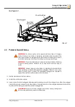
The hydraulic control levers become operational when the contacts at the bottom of the carriage touch the
power strip on the frame tube. The hydraulic control levers will only work when the cutting head is close
enough to the front end of the mill to touch the power strip.
See Figure 2-15.
DH3 hydraulic units have six control levers to load, clamp, turn and level logs. DH5
and DH7 hydraulic units have four additional levers for controlling the Pull-Down clamps. In sawmills
equipped with DH5 hydraulic system, individual Pull-Down clamps are controlled with separate
levers. In sawmills with DH7 hydraulic system, in/out movement of individual clamps is controlled
with the same lever and up/down movement of individual clamps is controlled with separate levers.
DH5 and DH7 hydraulic control boxes are equipped with an oil flow control valve.
FIG. 2-15
Clamp In/Out
Clamp Up/Down
Turner
Front Toeboard
Rear Toeboard
Loader


