


ActiveScale™ P100 Support Guide
46
1. Remove the blanking panel from the System Interconnect mounting kit.
a. Remove the thumb screw from the front of the blanking panel.
b. Grasp the blanking panel by the front cutouts.
c. Pull the blanking panel from the mounting kit.
Note:
You might have to remove adjacent blanking panels to fully access the 3U
mounting kit or System Interconnects.
2. At the rear of the rack, remove the network cables from the front of the System Interconnect.
3. At the front of the rack, remove the power cords from the rear of the System Interconnect.
4. Locate and unscrew the retention screws on the front of the system that secure the 3U mounting kit
adapter to the rack.
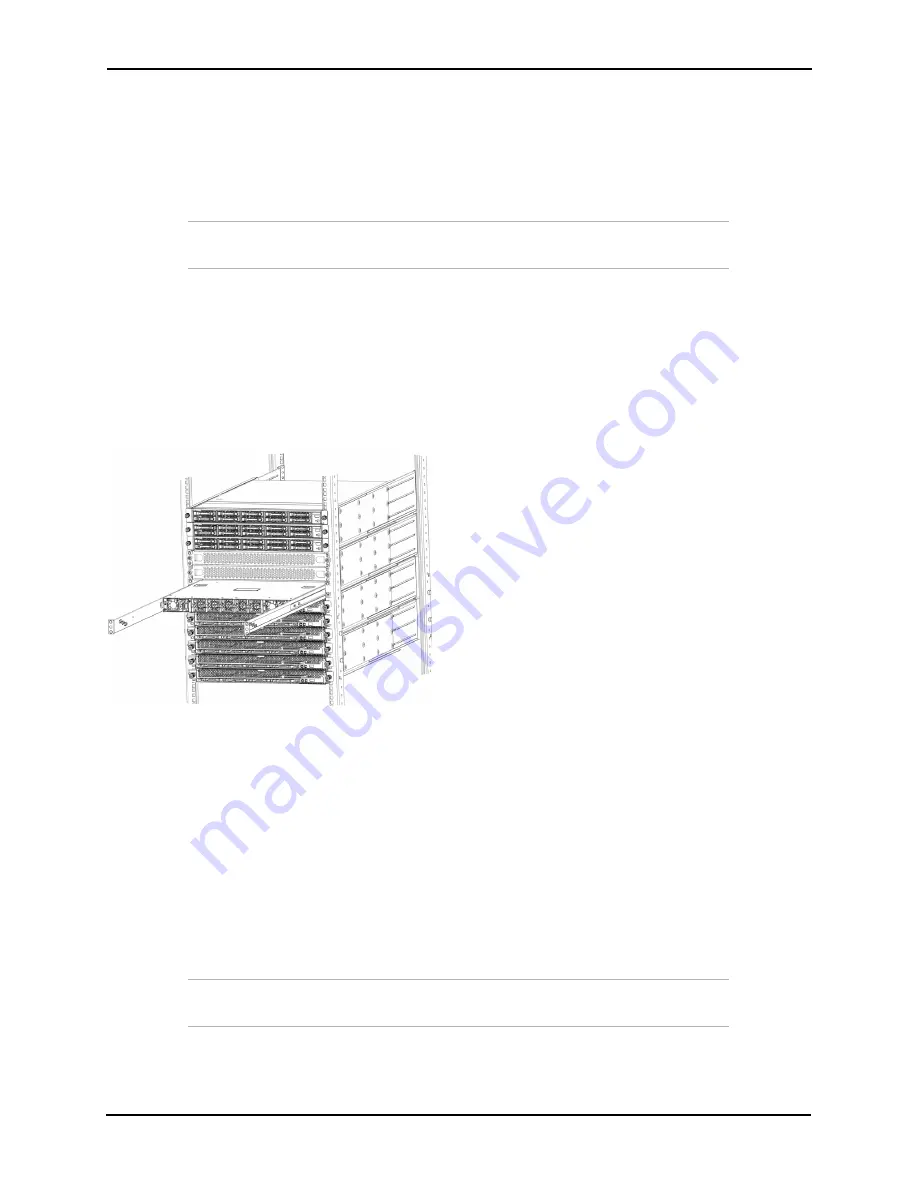
5. Gripping the System Interconnect firmly with both hands, pull forward with even pressure until it
releases from the rack.
Figure 3-32. Removing System Interconnects
6. Record the serial number on the faulty component for return purposes.
3.2.4.2 Installing a System Interconnect
To install a replacement System Interconnect:
1. Align the replacement System Interconnect with the empty space in the rack and slide it completely
into the rack.
2. From the front of the rack, reconnect the two power cords to the back of the System Interconnect.
3. Secure the blanking panels using the thumbscrews.
4. Reconnect all of the networking cables using the
Cabling Map
on page 66.
3.2.4.3 Programming a System Interconnect
Important:
The steps in this section are only required if you are replacing
System Interconnect 2.
Replacement System Interconnects are programmed to function as System Interconnect 1 in the rack. If
you are replacing System Interconnect 2, it must be reprogrammed.
Summary of Contents for ActiveScale P100
Page 103: ...ActiveScale P100 Support Guide 101...
Page 104: ...ActiveScale P100 Support Guide 102...
Page 120: ...ActiveScale P100 Support Guide 118...
Page 124: ...ActiveScale P100 Support Guide 122...
Page 131: ...ActiveScale P100 Support Guide 129...
Page 132: ...ActiveScale P100 Support Guide 130...


