One power cord
9 pin D-Sub receptacle (solder cup) and metal hood
AC fuses (Two each for 115V or 230V operation)
50
Ω
BNC terminator (Analog version only)
Certifi cate of Calibration
5
This User’s Guide
Benchlink software (3.5” fl oppy included with this User’s Guide)
Preparing the Temperature Controller for Use
A
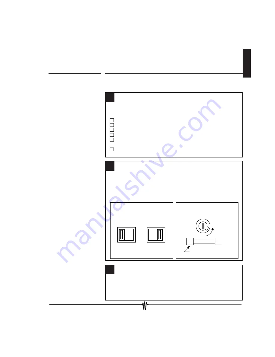
Verify you have received these items.
The following steps help you verify the temperature controller is ready for use.
B
Verify the power line voltage setting.
Remove power cord. Change
switch to proper voltage.
Remove fuse holder assembly
and verify fuse rating or install
proper fuse.
C
Connect power cord and power on the LFI-3751.
Chapter 1 - Quick Start
Preparing the Temperature Controller for Use
15
1
Ensure the power source you plug the temperature controller into is properly
grounded. Once the
AC Power Switch
on the front panel is pressed in,
all LEDs on the front panel will light up while the temperature controller
performs its power-on self test. After the test, the temperature controller
is ready for normal operation.
The line voltage is set to the proper value for your country when the
temperature controller is shipped from the factory. The available settings
are 115 or 230 VAC. If the voltage setting is incorrect, change it and check
that the correct fuse is installed. If fuses are not available locally, call
the Wavelength Electronics Technical Support Group or your international
distributor to order new fuses.
If anything is missing, contact Wavelength Electronics or your nearest
international distributor.
115V
230V
OR
Remove with
a screwdriver
2000 maT for 115 V
1000 maT for 230 V
5 x 20 mm SLO BLO
Summary of Contents for LFI-3751
Page 10: ...10 This page intentionally left blank ...
Page 13: ...1 Chapter 1 Quick Start 13 1 ...
Page 20: ...20 This page intentionally left blank ...
Page 21: ...2 Chapter 2 Front Panel Operation 21 2 ...
Page 34: ...34 This page intentionally left blank ...
Page 54: ...54 This page intentionally left blank ...
Page 68: ...68 This page intentionally left blank ...
Page 69: ...3 Chapter 3 Rear Panel Operation 69 3 ...
Page 75: ...3 4 Chapter 4 Remote Interface Reference 75 4 ...
Page 88: ...88 This page intentionally left blank ...
Page 127: ...5 Chapter 5 Specifications 127 5 ...
Page 131: ...Appendix CAT 220 Cable Accessory Diagram 131 ...


