background image

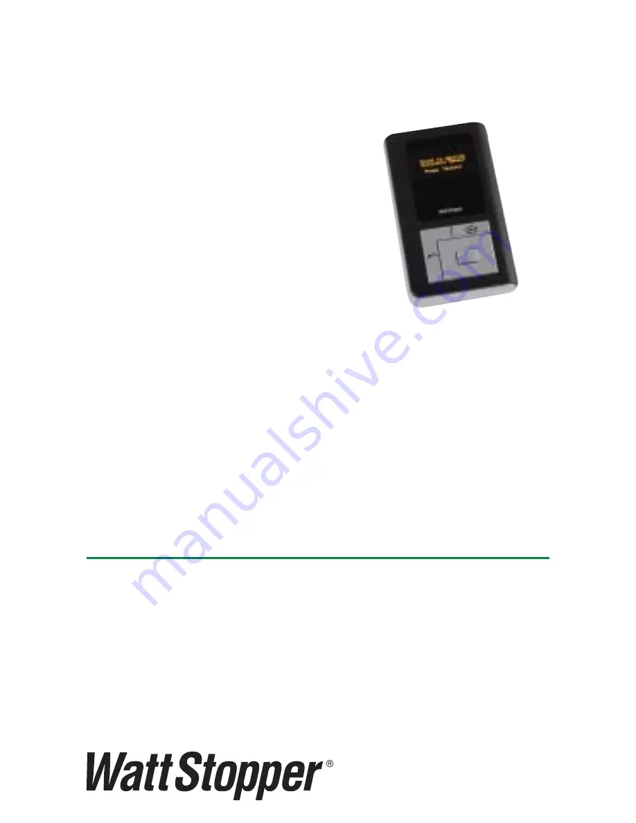
The LMCT-100 Wireless IR 
Confi guration Tool is a handheld 
tool for setup and testing of 
WattStopper Digital Lighting 
Management (DLM) devices. 
It provides wireless access 
to occupancy and daylighting 
sensors for setup and parameter 
changes, WattStopper Push n’ Learn™ (PnL) 
technology for load confi guration, switch and 
dimmer assignment and operating parameter 
changes. The LMCT-100’s display shows menus 
and prompts to lead you through each process. 
The navigation pad provides a familiar way to 
navigate through the customization fi elds. The 
LMCT-100 allows modifi cation of the system 
without requiring ladders or tools; simply with a 
touch of a few buttons.

User  Guide

LMCT-100

Digital Confi guration Tool

Patents Pending

Sensor Configuration............... 4
Load Configuration (PnL)  ..... 13
Daylighting Configuration ...... 17
Button Configuration ............. 78
Dimming Configuration ......... 85
Adjust Light Level .................. 90
Network Settings ................... 91
Utilities ................................... 70
Troubleshooting ..................... 73

CONTENTS

Summary of Contents for LMCT-100

Page 1: ...he LMCT 100 s display shows menus and prompts to lead you through each process The navigation pad provides a familiar way to navigate through the customization fields The LMCT 100 allows modification of the system without requiring ladders or tools simply with a touch of a few buttons U s e r G u i d e LMCT 100 Digital Configuration Tool Patents Pending Sensor Configuration 4 Load Configuration PnL 1...

Page 2: ... 100 can also set or change the daylight level parameters The LMCT 100 can change dimming system options such as scene assignments fade rates and other options not available through the standard user interface BATTERIES The LMCT 100 operates on three standard 1 5V AAA Alkaline batteries or three rechargeable AAA NiMH batteries The battery status displays in the upper right corner of the display Th...

Page 3: ...e key beyond maximum or minimum values Moving away from the value field using keys overwrites the original value The button takes you to the main menu The button can be thought of as an un do function It takes you back one screen Changes that were in process prior to pressing the key are lost Sensor Configuration Load Config PnL Daylighting Config Button Configuration Dimming Configuration Adjust L...

Page 4: ...ss Select Sensor Configuration Load Config PnL Daylighting Config Button Configuration Dimming Configuration More BAT This action enables com munication between the sensor and the LMCT 100 The sensor immediately sends its current parameter settings The screen changes to show the current sensor settings where you can adjust sensor parameters AH next to Sensor Config indicates that the sensor is curr...

Page 5: ... 20 min PIR Sens 90 US Sens 70 Trigger PIR Only Retrigger PIR Only Walkthru Off SEND SAVE RECEIVE Adjust PIR Sensitivity Adjust Ultrasonic Sensitivity Sensor Config Time Delay 20 min PIR Sens 90 US Sens 70 Trigger PIR Only Retrigger PIR Only Walkthru Off SEND SAVE RECEIVE Press the Down Arrow for Ultrasonic Step 1 push or to adjust the value PIR and Ultrasonic sensitivities vary from 0 to 100 in 1...

Page 6: ... Retrigger PIR Only Walkthru Off SEND SAVE RECEIVE Walk Through Mode On or Off Press the down arrow to choose Send Save or Receive Walk through mode turns the load off three minutes after the area is initially occupied if no motion is detected after the first 30 seconds If motion continues beyond the first 30 seconds the selected time delay applies Sensor Config Time Delay 20 min PIR Sens 90 US Sens...

Page 7: ...ings were sent to the sensor see Receive Save Sensor Config Time Delay 20 min PIR Sens 90 US Sens 70 Trigger PIR Only Retrigger PIR Only Walkthru Off SEND SAVE RECEIVE Choose Save Press Select Point and Press Select Saved Sensor Config in Memory Slot 1 Press Select This saves the settings in the LMCT 100 Saved Configurations menu function for future use Each time you save a configuration the Memory ...

Page 8: ...Select Point and Press Select This retrieves the current settings from the sensor SENSOR CONFIGURATION TEST MODE Sensor Testing Individual Sensor Sensor Configuration Current Settings Test Mode Saved Configurations Press Select Press Select Press the Down Arrow for Test Mode Point to desired Occupancy Sensor Press Select Sens or Test Mode Indi vi du al Sen sor All Sen sor s on bu s Point and Press...

Page 9: ... Sensor Test PIR Sens 90 US Sens 70 Detection PIR Only SEND RECEIVE EXIT Sensor Test PIR Sens 90 US Sens 70 Detection PIR Only SEND RECEIVE EXIT You can adjust sensitivity values while inside the Test Mode Values are 0 to 100 in 10 increments Detection Criteria Dual Technology Sensors only Select Detection technology Press down arrow for Detection Sensor Test PIR Sens 90 US Sens 70 Detection PIR U...

Page 10: ...n PIR Only SEND RECEIVE EXIT Con fi g u rat i o n S en t Test Mode starts using the settings you sent Receive Choose Receive Press Select Point and Press Select Point to desired Occupancy Sensor Press Select Sensor Config Time Delay 20 min PIR Sens 90 US Sens 70 Trigger PIR Only Retrigger PIR Only Walkthru Off SEND SAVE RECEIVE Sensor Test PIR Sens 90 US Sens 70 Detection PIR Only SEND RECEIVE EXI...

Page 11: ...IR Sens 90 US Sens 70 Detection PIR Only SEND RECEIVE EXIT Choose Exit Press Select Point and Press Select Sensor Testing All Sensors on Bus Press Select Point to any Occupancy Sensor Press Select Sensor Test Mode Individual Sensor All Sensors on bus Point and Press Select When you select All Sensors on bus you can test the selected sensor along with other sensors on the DLM Local Network bus to u...

Page 12: ... To Review the Config Settings Select RECALL Press Select Press Select To Delete the Saved Config Select DELETE Press the Right or Left Arrow to view other Saved Configs Sa ved Sensor Confi gs Pic k DT Saved Confi g 2 5 8 0 7 0 R ECALL DELETE Sa ved Sensor Confi gs Pic k DT Saved Confi g 2 5 8 0 7 0 R ECALL DELETE Sensor Config Time Delay 5 min PIR Sens 80 US Sens 70 Trigger PIR US Retrigger PIR or U...

Page 13: ...en abled device on th e n etwork Press Select Sensor Confi guration Load Confi g PnL Daylighting Confi g Button Confi guration Dimming Confi guration More BAT When the device receives the signal from the LMCT 100 the DLM Local Network goes into PnL mode the red LED on all communicating devices starts blinking at 2x second and all loads turn OFF except Load 1 turns ON Load Selection Settings for lo...

Page 14: ...ime delay expires Push or to adjust the Blink Warning Options are Disable and Enable LMLS 105 Load Config PnL Load 1 Operation Auto On Blink Disable LMLS 105 Disable SEND BIND NEXT EXIT Daylighting Disable or Enable This function enables and disables an LMLS 105 daylighting sensor to control the selected load Load Config PnL Load 1 Operation Auto On Blink Disable LMLS 105 Disable SEND BIND NEXT EX...

Page 15: ...HOME to exit PnL Load Config PnL Load 1 Operation Auto On Blink Disable LMLS 105 Disable SEND BIND NEXT EXIT Choose Bind Press Select Point to desire d Occupancy Sensor to bind to Load Point and Press Select Press Select Send New settings have been sent to the selected load Wait 5 6 seconds for the message to clear Select another function bind next exit To instantly end load configuration press the...

Page 16: ...d 1 Operation Auto On Blink Disable LMLS 105 Disable SEND BIND NEXT EXIT Choose Next Press Select Press Select Choose desired Load Point to any IR enabled device Press Select Select Load Load 2 Adjust settings as necessary Press Select Load Config PnL Load 2 Operation Manual On Blink Disable LMLS 105 Disable SEND BIND NEXT EXIT Load Config PnL Load 2 Operation Manual On Blink Disable LMLS 105 Disa...

Page 17: ...ht sensors in high bay applications it is important to stand directly underneath the photosensor with the LMCT held in a vertical orientation pointed at the bottom of the sensor In some cases direct communications between the LMCT and the LMLS 600 may be difficult to achieve due to interference from very high ambient light when looking up from direct sunlight high intensity fluorescent fixtures e g T...

Page 18: ...nting the Light level Day Setup D ayligh t in g C on fi g L M L S 3 0 5 L S 3 0 1 When don e adju st in g press S elect Day S et u p Press Select Daylighting Config LMLS 305 LS 301 Day Setup Day Setpoint Saved Press Up or Down arrow to adjust light level Increment raise Decrement lower D aylight ing Config LMLS 305 LS 301 LMLS 400 LMLS 500 LMLS 600 Press Select Choose LMLS 305 LS 301 Daylighting C...

Page 19: ... onfi g LMLS 305 LS 301 D e c re me nting the Light le v e l N ight Se tup Daylighting Config LMLS 305 LS 301 W hen done adjusting press Select Night Setup Press Select D a y lighting C onfi g LMLS 305 LS 301 N ight Se tup N ight Se tpoint Sa ve d Press Up Down arrow to adjust light level Daylighting Config LMLS 305 LS 301 Choose setpoint press Select Se t up Day Press Left Right arrow to scroll t...

Page 20: ...g Config LMLS 305 LS 301 Automatic Mode Enabled Daylighting Config LMLS 305 LS 301 Choose setpoint press Select Se t up Day Press Left Right arrow to scroll to Auto Setpoint Press the Home Button to return to the Home Page Press Home Dayl i gh t i n g Con fig LML S 3 0 5 L S 3 0 1 Ch oose set poi n t press Sel ect Setup A u t o Sensor Configuration Load Config PnL Daylighting Config Button Configu...

Page 21: ...ress Select S e n sor Configuration L oa d Config PnL Da y lighting Config Bu tton Configuration Di m ming Configuration More BAT Choose LMLS 400 Choose Daylighting Config Specific Photosensor Press Select Dayligh tin g L ML S 4 00 Spe c ifi c Ph otose n sor Searc h Ph otose n sor s Poi nt t o t he desi re d Phot osensor and press Sel ect Point and Press Select Serial number will be different for ea...

Page 22: ...ylig hting LMLS 40 0 Spe c ific Photose nsor Searc h Photose nsors Point to Any IR enabled device on the network Press Select Point and Press Select Press Select Choose Search Photsensors Daylig hting LMLS 40 0 Se le c t a d e vic e I D 0293724909 Press Select Choose Desired Photsensor Point to Any IR enabled device on the network Press Select Point and Press Select LMLS 400 Daylighting Menu Seria...

Page 23: ...lect LML S 400 02936119 35 Zone S e tup Calibra tio n Zone S e ttings Adva nc e d S e ttings Con tro l M o de Zone Set up LMLS 400 Oper at ion Dimmed CONTINUE Press Left Right arrow to scroll to the desired operation mode Switched Bi Level Tri Level or Dimmed Point and Press Select Zone S e tup LM LS 400 O pera tio n S witc hed C O N T IN U E Press Select Choose CONTINUE Point t o any IR enabled d...

Page 24: ...the daylighting zone controlled by the photosensor Load 1 OFF 0 Load 1 ON 100 Bi Level Bi level mode provides three light levels within the daylighting zone controlled by the photosensor by using 2 load circuits Load 1 OFF Off 0 Med 50 Max 100 Load 2 OFF Load 1 ON Load 2 OFF Load 1 ON Load 2 ON ...

Page 25: ...ing zone controlled by the photosensor by using 2 load circuits Dimmed Dimmed mode provides continuous dimming within the daylight zone controlled by the photosensor Load 1 ON 1 1 100 Load 1 ON 100 Off 0 Low 33 High 66 Max 100 Load 1 OFF Load 2 OFF Load 1 OFF Load 2 ON Load 1 ON Load 2 OFF Load 1 ON Load 2 ON ...

Page 26: ... 1 Daylight Load No NEXT PRIOR DONE Press Left Right arrow to choose Yes or No Depending on the Operation Mode the screen display will be Switched or Dimmed Load 1 Z one Setup LMLS 400 Swi tched To do load binding the load needs to be assigned as a Daylight Load by selecting Yes Load 1 Daylight Load Yes NEXT PRIOR DONE Zone Setup LM LS 400 S w itched ...

Page 27: ...ight Load No NEXT PRIOR DONE Zone settings for the next load is diplayed Zone Setup LMLS 400 Switched Load 1 Daylight Load Yes NEXT PRIOR DONE Zone Setup LMLS 400 Switched Point to an IR enabled device on the Network Press Select Prior To continue to assign Daylight Load binding to the previous load choose PRIOR This function behaves the same for all Operation Modes ...

Page 28: ...hed Done When you have completed all load bindings choose DONE This function behaves the same for all Operation Modes Poin t to an IR en abled device on th e N etwork an d Press S elect Point and Press Select Zone Setup settings have been saved The screen returns to the Daylighting Parameters menu Press Select Choose DONE Lo a d 1 Da y light Load N o NEXT PRIOR DONE Zo ne Setup LMLS 400 Switched L...

Page 29: ...do load binding the load needs to be assigned as a Daylight Load by selecting Yes Next Prior and Done process is the same as Switched and Dimmed Tri Level Load Assignment Load 1 Dayli g ht Lo a d N o NEX T PRI OR DON E L oad 1 D ay ligh t L oad Yes O n Wh en L ow Max N EX T P RIO R D O N E Zon e Setu p L ML S 4 0 0 Tri L evel Zone S e t up LMLS 40 0 Tr i Le v e l Press Left Right arrow to choose Y...

Page 30: ...oint and Press Select Zone Setup settings have been saved The screen returns to the Daylighting Parameters menu Press Select Choose DONE Lo a d 1 Da y light Load N o NEXT PRIOR DONE Zo ne Setup LMLS 400 Switched LMLS 400 02936119 3 5 Zo ne Setup Calibration Zo ne Settings Ad v anced Settings Co ntrol Mode Poin t to an y IR en abled device on th e N etwork Press S elect ...

Page 31: ... LMLS 500 Numb e r o f Zo ne s 3 C ONT IN U E Press Left Right arrow to select the number of Zones 1 2 or 3 Po int to Any IR e na b le d d e vic e o n the ne two r k Pre ss S e le c t C ho o se the numb e r o f D a y lig hting Zo ne s Zone Setup LMLS 500 Zone 1 Bi Level Zone 2 Switched Zone 3 Tri Level CONTINUE P ick a control type for ALL Zones Zo ne S e tup LMLS 500 B i Le ve l NEXT PRIOR DON E ...

Page 32: ...el or Dimmed Switched Switched mode provides ON OFF switching within the daylighting zone controlled by the photosensor Load 1 OFF 0 Load 1 ON 100 Bi Level Bi level mode provides three light levels within the daylighting zone controlled by the photosensor by using 2 load circuits Load 1 OFF Off 0 Med 50 Max 100 Load 2 OFF Load 1 ON Load 2 OFF Load 1 ON Load 2 ON ...

Page 33: ...one controlled by the photosensor by using 2 load circuits Dimmed Dimmed mode provides continuous dimming within the daylight zone controlled by the photosensor Load 1 ON 1 1 100 Load 1 ON 100 Off 0 Low 33 High 66 Max 100 Load 1 OFF Load 2 OFF Load 1 OFF Load 2 ON Load 1 ON Load 2 OFF Load 1 ON Load 2 ON ...

Page 34: ...play will be Switched or Dimmed Load 1 Zone Setup LMLS 500 Swi tched Next To continue to assign Daylight Load binding to load 2 choose NEXT Zone Setu p LMLS 500 Dimmed N EXT PRIOR DONE Load 2 Zone 2 Zone Setu p LMLS 500 Switched N EXT PRIOR DONE Load 1 Zone 1 Press Select Choose NEXT Point and Press Select Zone settings for the next load is diplayed Point to an IR enabled device on the Network Pre...

Page 35: ...Select Point and Press Select Zone Setup settings have been saved The screen returns to the Daylighting Parameters menu LML S 500 0293611935 Zo ne Setup Cal ibr ation Zo ne Settings Advanced Settings Control Mode Point to any IR enabled device on the Network Press Select Zo ne Setup LMLS 500 Switched NEXT PRIOR DONE L o ad 1 Zone 1 Press Select Choose DONE Zone Setup LMLS 5 00 Switched NEX T PR I ...

Page 36: ...mmed Load 1 Press Left Right arrow to select the Zone Zone Setup LMLS 500 Bi Level NEXT PRIOR DONE Load 1 Zone 1 On When Max Zone Setu p L ML S 500 Bi L evel NEX T P R I O R DO N E Load 1 Zone 1 On Wh en Med Max Zone Setup LMLS 500 Bi Lev el N EXT PRIOR D ON E Load 1 Zone 1 On When Med Max Press Select Choose NEXT Bi level and Tri Level only Press the Down arrow for On When to appear Press Left Ri...

Page 37: ... Tri Level only Press the Down arrow for On When to appear Zone Setup LMLS 5 00 Bi Level NEXT PR I O R D O N E Load 1 Zone 1 On When Med Max Press Select Choose NEXT Point and Press Select Zone settings for the next load is diplayed Point t o an IR enabled dev ice on t he Net w ork Press Select Press Left Right arrow For Bi Level select Med Max or Max For Tri Level select Low Max or High Max ...

Page 38: ...On When Max Press Select Choose PRIOR Point and Press Select Point t o an IR enabled dev ice on t he Net w ork Press Select Point to an IR enabled device on the Network and Press Select Point and Press Select Zone Setup settings have been saved The screen returns to the Daylighting Parameters menu LML S 500 0293611935 Zo ne Setup Cal ibr ation Zo ne Settings Advanced Settings Control Mode Point to...

Page 39: ...r activate automatic calibration from the LMCT 100 3 Blue LED will start flashing once every 4 sec 4 Daylighting controlled loads will automatically turn ON for 2 minutes to allow controlled lamps to warm up and reach a stable full output 5 Remove any objects that may affect the LMLS 400 light level reading ladder or temporary objects 6 Lights will cycle eight times for automatic setpoint selection...

Page 40: ... ON for 2 min then Auto Calibration will take 2 more min to finish Please wait 120 sec Counts down from 120 seconds then returns to the Main Menu the Automatic Calibration process continues for 2 minutes with the controlled loads switching ON and OFF then the sensor enters Test Mode for 5 minutes Calibrating LMLS 400 Manual Calibration Press Select Press Select LMLS 400 0293611935 Zone S e tu p Ca...

Page 41: ...el at at the workplane 35fc SEND Press Select To set the On and Off Setpoints automatically to best match a designed light level for the workplane enter the desired level along with the present measured level from a light meter and then press SEND Dimmed Press Select Daylighting Confi g LMLS 400 Choose setpoint press Select Setup Day Point to the desire d photosensor and continue to point to it du...

Page 42: ... button 2 Using a light meter at the task surface press the Up and Down LMCT 100 arrows to adjust light levels 3 Once the target level has been reached press the Select button to hold the value 4 When Day and Night adjustments are complete press HOME to terminate the calibration process and return to normal operation To set the desired light level point to the LMLS 400 and continue pointing to it ...

Page 43: ...eys to set the desired Day light level Daylighting Config LMLS 400 Incre menting the Light level Day Setup Daylighting Config LMLS 400 Day Setup Day Setpoint Saved Continue adjusting pressing the Up or Down arrow until desired Light Level is achieved Night Setup To set the desired light level point to the LMLS 400 and continue pointing to it while pressing the keys The key increments and the key d...

Page 44: ... to set the desired Day light level Daylighting Config LMLS 400 Incrementing the Light level Night Setup Continue adjusting pressing the Up or Down arrow until desired Light Level is achieved Daylighting Config LMLS 400 When done adjusting press Select Night Setup Press Select When Day and Night adjustments are complete press the HOME key to terminate Manual Calibration and return to normal operat...

Page 45: ...LMCT 100 for the Calibration process 1 Complete all wiring and turn power ON to the connected room controllers 2 SelecttheLMLS 500tobecalibratedusingtheLMCT 100 3 Select Calibration For each Zone choose a reference location that is most likely to have the lowest light level when daylit for each zone Light Level at Photocell 0 20 40 60 80 100 0 500 1000 1500 2000 1750 70 Light Level at Task ...

Page 46: ...communication with the LMLS 500 Press Select L MLS 500 0293724909 Z o ne Set up C alibrat ion Z o ne Set t ings Ad v anced Set t ings C on trol M ode Choose Calibration Light s will warm up and remain ON for t wo minut es Pleas e wait 120 s ec Counts down from120 seconds then returns to the Main Menu Enter light level for ALL zones C alibrat ing LMLS 500 Point to Any I R enabled device on the netw...

Page 47: ...a similar menu in LMCS or by pressing and holding the user pushbutton located on the bottom of the sensor farthest from the RJ45 connection for three seconds Sens or Configuration Load Config PnL Daylighting Config Button Configuration Dimming Configuration More BAT Press Select Press Select LMLS 600 0293611935 Zo n e Setup Calibr ation Zo n e Settings Ad vanced Settings Co n trol Mode Choose Cali...

Page 48: ...der the sensor Turning off all configured loads for about 10 seconds to compute an initial daylight ratio Warming up the controlled loads at maximum level until they reach full output typically this requires several minutes Switching or Fading the level of the controlled loads from maximum to minimum level very slowly over approximately two minutes while observing both sensors to determine the ball...

Page 49: ...alibration Choose Calibration Daylighting LMLS 600 Automatic Calibration Manual Calibration Choose a reference location within the daylighting zone that is most likely to have the lowest light level when daylit and is located farthest from the window Point to any IR enabled device on the network Press Select Cal i brating LMLS 600 Desi red Light Level at t he workplane 50fc A ct ual Light Level at...

Page 50: ...ode Choose Zone Settings When Zone Settings is selected one of two screens is displayed depending on the Operation Mode of the device Switched Bi Level or Tri Level or Dimmed Switched Bi Level or Tri Level ON Setpoint The target illuminance level at the sensor below which the photosensor turns the lights ON Daylight ing LMLS 4 0 0 Bi Level SEND ON Set point OFF Set point ON Time D elay OFF Time D ...

Page 51: ...o the ON Setpoint multiplied by 1 25 1 50 1 75 or 2 0 This ensures that the OFF Setpoint is always higher than the On Setpoint ON Time Delay The time interval that must elapse with the measured level below the ON Setpoint before the controlled lights turn on Range 1 sec to 60 sec Daylighting LMLS 400 Bi Level SEND ON Setpoint OFF Setpoint ON Time Delay OFF Time Delay 7 5fc 11fc 20sec 10min Press L...

Page 52: ...in Press the Down Arrow to choose SEND Point and Press Select LMLS 400 0293611935 Zo ne Setup C alibration Zo ne Settings Ad v anced Settings C o ntrol Mode LMLS 400 Daylighting Menu Zone Settings have been saved The screen returns to the Daylighting Parameters menu Point to any IR enabled device on the Network Press Select Daylighting LMLS 400 Bi Level SEND ON Setpoint OFF Setpoint ON Time Delay ...

Page 53: ... for any given photocell reading it calculates the level based on the slope between the day and the night setpoint Range 1 fc to 255 fc Note The Day Setpoint must always be greater than the Night Setpoint Day l i ghti ng LM LS 400 Di m m ed SEND Day Setpoi nt Ni ght Setpoi nt R am p Up R am p Down Cut Off Del ay 50fc 10fc 20 s ec 2 s ec 10m i n Press Left Right arrows to increase or decrease footc...

Page 54: ...creases The default is 2 per second because a slow ramp down will help the eye adapt to the new light level Range 1 per second to 100 per second Daylighting LMLS 400 Dimmed SEND Day Setpoint Night Setpoint Ramp Up Ramp Down Cut Off Delay 50fc 10fc 20 sec 2 sec 10min Press Left Right arrows to increase or decrease Fade Up time 5sec 60sec Daylighting LMLS 400 Dimmed SEND Day Setpoint Night Setpoint ...

Page 55: ...sec 10min Press the Down Arrow to choose SEND Point and Press Select LMLS 400 0293611935 Zo ne Setup C alibration Zo ne Settings Ad v anced Settings C o ntrol Mode LMLS 400 Daylighting Menu Zone Settings have been saved The screen returns to the Daylighting Parameters menu Point to any IR enabled device on the Network Press Select Daylighting LMLS 400 Dimmed SEND Day Setpoint Night Setpoint Ramp U...

Page 56: ...tched Bi Level or Tri Level ON Setpoint The target illuminance level below which the LMLS 500 turns the lights ON Range 5 to 150 fc Day l i gh t i n g L M L S 500 Zon e 1 B i L e ve l O N S e t poi n t O FF S e t poi n t O N Ti me De l a y O FF Ti me De l a y 35fc 53fc 20 se c 10 mi n SEN D NE XT Z O NE DO NE Daylighting LMLS 500 SEND NEXT ZONE DONE Setpoint Ramp Up Ramp Down Cut Off Delay 50fc 20...

Page 57: ...ed level above the OFF Setpoint before the controlled lights turn OFF Range 3 min to 30 min Press Left Right arrow to raise or lower ON Time Delay 1sec 60sec ON Setpoint OFF Setpoint ON Time Delay OFF Time Delay 35fc 53fc 20 sec 10 min Daylighting LMLS 500 Zone 1 Bi Level SEND NEXT ZONE DONE Press Left Right arrow to raise or lower OFF Time Delay 3min 30min O S etpoint OFF S etpoint ON Time Delay ...

Page 58: ...rk Press Select O Setpoint OFF Setpoint ON Time Delay OFF Time Delay 7 5fc 11fc 20 sec 10 min Daylighting LMLS 500 Zone 1 Bi Level SEND NEXT ZONE DONE Dimmed Setpoint The desired light level at the task per zone To determine the correct dimming level for any given photocell reading it calculates the level based on the slope between the daylight contribution at the sensor and the setpoint Range 5 t...

Page 59: ...wn will help the eye adapt to the new light level Range 1 per second to 100 per second Cut Off Delay The time that the controlled lighting will remain at a minimum dimmed level even with high daylight contribution before the lights will be switched OFF Range Never to 30 min Send Press the SEND button to save the new settings Daylighting LMLS 500 SEND NEXT ZONE DONE Setpoint Ramp Up Ramp Down Cut O...

Page 60: ...pending on the Operation Mode of the Zone Switched or Dimming Bi Level or Tri Level Switched Bi Level or Tri Level Dimmed Switched Bi Level or Tri Level ON Setpoint The target illuminance level below which the LMLS 600 turns the lights ON Range minimum of 1 fc maximum of 32 fc for Switched or 48 fc for Bi Level or Tri Level Daylighting LMLS 600 Switc he d ON Setpt OFF Setpt ON Time Dela y OFF Time...

Page 61: ...level above the OFF Setpoint before the controlled lights turn OFF Range 3 min to 30 min Press Left Right arrow to raise or lower OFF Setpoint footcandles ON Se tp t OFF Se tp t ON T i me D e l a y OFF T i me D e l a y 0 300fc 0 525fc 20 s e c 10 mi n D a yl i g hti ng LMLS 600 B i Le v e l SE N D Press Left Right arrow to raise or lower ON Time Delay 15 sec 60 sec ON Se t pt OFF Se t p t ON Time ...

Page 62: ...ve been saved The screen returns back to the previous menu Bi Level Poi n t to An y IR en abl ed devi ce on th e n etwork Pres s S el ect Dimmed Dimming Setpoint The desired light level is maintained by daylighting control as measured by the down looking sensor When the present measured light level differs from this setpoint by more than approximately 7 the sensor will attempt to adjust the electr...

Page 63: ...Delay The time that the controlled lighting will remain at a minimum dimmed level even with high daylight contribution before the lights will be switched OFF Range Never to 60 min D a ylig ht ing LMLS 600 SEND D imming SP Ra mp U p Ra mp D own C ut Off De la y 1 900fc 20 s e c 5 s e c N e ve r D imme d D a ylig ht ing LMLS 600 SEND D imming SP Ra mp U p Ra mp D own C ut Off De la y 1 900fc 20 s e ...

Page 64: ...ing control has been disabled due to an observed external user or system action before automatic control resumes Range Infinity or 1 to 24 hours Press Select LMLS 400 0293611935 Zone Setup Calibration Zone Settings Advanced Settings Control Mode Choose Advanced Settings Daylighting LMLS 400 SEND Light Level Allow Override Override Time Hold Off Scenes Stop DL Ignore Aft Hrs 10 fc Yes Infin No No No...

Page 65: ...oint but will become active for daylighting control and will turn ON or dim up as daylight contribution drops Scenes Stop DL When set to No the sensor allows daylighting to adjust light levels up to the level recorded in the Scene even though a scene is active When set to Yes daylighting control is disabled for any loads on which a scene is recalled until a change is manually made to the level of ...

Page 66: ... from daylighting control while in the After Hours state Send Press the SEND button to save the new settings LMLS 4 0 0 0 2 9 3 6 1 1935 Zone S etup Calibration Zone S ettings Advanced S ettings Control M ode LMLS 400 Daylighting Menu Ignore After Hours have been saved The screen returns to the Daylighting Parameters menu Choose SEND then Press Select Daylighting LMLS 400 Daylighting LM LS 400 S E...

Page 67: ...to 65 fc Allow Override Determines if override mode is permited while daylighting control is active Available choices Yes or No Press Select LM LS 600 0293611935 Zone S etup Calibration Zone S ettings A dv anced S ettings Control M ode Choose dvanced Settings Daylighting LMLS 600 SEND NEXT 2 0fc 3 990fc Allow Override Override Time Hold Off Scenes Stop DL Ignore Aft Hrs Yes Infin No No No Daylight...

Page 68: ... and then will begin to adjust based upon daylight If Hold Off Yes the sensor will limit the loads to the level presently allowed by daylight contribution This means that the loads may not initially turn ON if the ambient light level is high above the ON or Dimming Setpoint but will become active for daylighting control and will turn ON or dim up as daylight contribution drops Daylighting LMLS 600...

Page 69: ...tosensor will ignore After Hours and will continue to operate as normal When set to No the daylighting controlled loads that are set to After Hours are removed from daylighting control for the duration of the After Hours period D ay lig h tin g L M L S 600 SEN D N EX T 2 0f c 3 990f c A llo w Ov er r id e Ov er r id e T im e H o ld Off Scen es Sto p D L I g n o re A f t H r s Yes I n fi n N o N o ...

Page 70: ...NEX T Point and Press Select Point to Any IR enabled device on the network Press Select Next To set the Recommissioning Threshold and Recommissioning Delay choose NEXT Press Select Choose NEXT Dayl ight ing LM LS 600 Max E L Light Daylight Ra t io Force Ope n Loop Recom m Thre sh Recom m D e la y Enab D ia g M sgs 1 833fc 0 0762 No 2fc 0m in Al l N EXT SEN D Point and Press Select LMLS 600 0293725...

Page 71: ...king sensor and that measured by the open loop up looking sensor D ay lig hting LMLS 600 M ax EL Lig ht D ayl ig ht Ratio F orce Op en Lo o p R eco mm T hresh R eco mm Delay En a b Diag Msg s 1 833fc 0 0762 No 2fc 0min All NEXT SEND Average Daylight Ratio of the closed loop daylight only and the open loop Maximum Electric Ligh shown in footcandles Daylighting LMLS 600 Max EL Light Daylight Ratio F...

Page 72: ...level below which the LMLS 600 enters recommissioning mode If this parameter is set to 0 automatic daily recommissioning is disabled Range 0 to 255 Daylighting LMLS 600 Max EL Light Daylight Ratio Force Open Loop Recomm Thresh Recomm Delay Enab Diag Msgs NEXT SEND 1 833fc 0 0762 Yes 2fc 0min All Press Left Right arrow to choose Yes or No Daylighting LMLS 600 Max EL Light Daylight Ratio Force Open ...

Page 73: ...ed by WattStopper technicians Send When you have completed adjusting the settings choose SEND Press Left Right arrow to raise or lower Recomm Time Delay 0min 240min D a y l i g h t i n g L M L S 6 0 0 M a x E L L i g h t D a y l i g h t R a t i o F o rc e O p e n L o o p R e c o m m T h re s h R e c o m m D e l a y E n a b D i a g M s g s N E X T S E N D 1 8 3 3 f c 0 0 7 6 2 Ye s 1 0 f c 2 0 m i ...

Page 74: ...u to select the control behavior of the photosensor After choosing Control Mode and pressing Select point to the LMLS device and press Select The current control mode is displayed This can be changed to Normal Test Demo or Disable D a y l i g h t i n g L M L S 4 0 0 C o n t ro l M o d e C o n t ro l M o d e N o r m a l S E N D C A N C E L Press Left Right arrow to scroll to the desired control mod...

Page 75: ...Calibration Z on e Settings Advanced Settings Co ntrol Mode Press Left Right arrow to choose SEND or CANCEL Control Mode has been saved The screen returns to the Daylighting Parameters menu Point to any IR enabled device on the Network Press Select Test Test Mode shortens timeouts for switching operation and speeds ramp rates for dimming operation to allow quick verification Test Mode cancels autom...

Page 76: ...Press Select Demo Demo mode will allow the photosensor to select a set of preset parameters This mode should only be selected when demonstrating the functionality of the unit is desired Dayli ght i n g LMLS 400 Cont rol Mode Con t rol Mode De mo S END CA NCEL Point and Press Select LMLS 400 0293724909 Zone Set u p Calibr a t i on Zone Set t i n gs Advance d Se t t i n gs Cont rol Mode Press Left R...

Page 77: ...s mostly used for troubleshooting purposes Dayli ght i n g LMLS 400 Cont rol Mode Cont rol Mode Di s abl e S END CA NCEL Point and Press Select LMLS 400 0293724909 Zone Set u p Calibr a t i on Zone Set t i n gs Advance d Se t t i n gs Cont rol Mode Press Left Right arrow to choose SEND or CANCEL Control Mode has been saved The screen returns to the Daylighting Parameters menu Point to any IR enabl...

Page 78: ...Blue LEDs on Switch Blink Continue Pointing at Switch Press Button The Button s LED Blinks Point at switch and Press Select Continue pointing to the switch then press the button you wish to configure Sensor Configuration Load Config PnL D ay lighting Config Button Configuration D imming Configuration More BAT Scene Button Button Type Example Rocker Scene 1 Scene 2 Scene 3 Load Rocker Button Rocker...

Page 79: ...ch time the button is pressed turns OFF the scene Note when Scene Off mode is set the blue LED on the button is never lit Recall OFF is similar to a toggle function pressing the button once when the scene is not active recalls the scene a subsequent button press while the scene is active turns OFF all members of the scene Scene Button Config Type Scene 1 Mode Recall Scene Lock Button No Fade On Us...

Page 80: ...imes independently for the same scene Application This feature allows the user to recall a scene quickly from one button but from another button the scene recall is much slower and gradual Fade time value options are from None immediate to 18 hours in duration As you scroll through the values the units of measure change from seconds to minutes to hours Scene Button Config Type Scene 1 Mode Recall ...

Page 81: ...N Press Select to bring up the screen instructing you to Point at switch and Press Select Follow the instructions on this screen Scene Button Config Type Scene 1 Mode Recall Scene Lock Button Yes Fade On Use Load s Fade Off Use Load s SEND NEXT BUTTON Choose SEND Press Select Point at Same Switch Press Select To Exit Press HOME Point at same switch Press Select Scene Button Config Type Scene 1 Mod...

Page 82: ...y mode each button press only causes the associated action In Toggle mode if there are multiple loads bound to a button and any load is ON the LED will be lit Pressing the button turns OFF all loads and the LED on the button turns OFF Pressing the button again turns ON all loads bound to the button Load Button Config Type Load Mode Toggle Fade On Use Load s Fade Off Use Load s SEND NEXT BUTTON Cho...

Page 83: ...scroll through the values the units of measure change from seconds to minutes to hours Send Next Button These selections are described on page 71 Rocker Button Parameters A rocker button or paddle is a type of load button It cannot be changed to be a scene button Parameter options are Fade On Fade Off and Ramp Rate Load Button Config Type Load Mode Toggle Fade On 10 sec Fade Off Use Load s SEND NE...

Page 84: ...f measure change from seconds to minutes to hours Ramp Rate Ramp Rate determines the speed or rate at which the light level of bound loads increases or decreases when the top or bottom of the rocker is pressed and held The default value is 17 second which means that it takes approximately 6 seconds to ramp from 0 100 Send Next Button These selections are described on page 59 Rocker Button Config F...

Page 85: ... default to Load Type Dim Be sure to select the appropriate load type because these room controllers can control either type of load Default settings are based on the load type selected Press Select Press Select Point to any IR enabled device on the network Press Select Sensor Configuration Load Config PnL D ay lighting Config Button Configuration D im ming Configuration More BAT Load 1 Dim Config...

Page 86: ...n 1 increments Preset Entering a Preset value causes the lights to go to this light level each time they are turned on By default the value is set to Last which turns the load on to its last used level The value options are Last or 1 100 in 1 increments Load 1 Dim Config Type Dim Low Trim 0 High Trim 100 Preset Level Last Burn in Hours 0 SEND PRIOR NEXT Choose Low Trim Last or 0 99 Load 1 Dim Conf...

Page 87: ...pond to dimming during this time Send Choosing Send and pressing Select saves the new settings to load 1 After pressing select the Point to any IR enabled device screen is presented From this screen you can either configure another load or exit Dimming Configuration by pressing the HOME or BACK buttons Load 1 Dim Config Type Dim Low Trim 0 High Trim 100 Preset Level Last Burn in Hours 100 SEND PRIOR...

Page 88: ...o scroll to PRIOR Press select Load 1 Dim Config Type Dim Low Trim 0 High Trim 100 Preset Level Last Burn in Hours 100 SEND PRIOR NEXT Choose NEXT Press Select To Configure Next Load Point at Device Press Select Point to any IR enabled device on the network Press Select Load 2 Dim Config Type Dim Low Trim 0 High Trim 100 Preset Level Last Burn in Hours 100 SEND PRIOR NEXT Choose PRIOR Press Select ...

Page 89: ...or OFF The value options are 1 25 75 51 or 100 The default is 51 Send Next Prior These selections are described on pages 65 66 Choose Switch Load 2 Dim Config Type Dim Low Trim 0 High Trim 100 Preset Level Last Burn in Hours 100 SEND PRIOR NEXT Load 1 Dim Config Type Switch Trip Point 51 Trip point alters when a relay switches during a fade SEND PRIOR NEXT Choose Desired Trip Point 1 25 51 75 or 1...

Page 90: ...he selected load a quick tap on turns OFF the load Pressing and holding ramps the light level up pressing and holding fades the light level down Adjus t Light Level Network Settings Utilities More BAT Adjust Light Level Load 1 LEFT RIGHT picks load UP DOWN adjusts level Press HOME when done Keep pointing to the device while adjusting Press the right or left arrow to select load The selected load q...

Page 91: ...ment Manager communicates with the DLM local networks and panels over a BACnet compatible digital segment network The LMSM 201 supports one segment network while the LMSM 603 supports three segment networks BACnet MS TP baud rate 9600 19200 38400 76800 or 115200 selectable Press Select LMBC 300 0016787229 Na me 0016787229 De vice ID 0086229 A ut oSet MSTPMAC Yes A ut o MSTP M AC 099 Ba ud Rate 384...

Page 92: ...e after hours or normal hours mode for testing Smart Wire The Smartwire feature is used to configure LMSW buttons and DLM occupancy sensors to control relays in the LILM series Lighting Integrator panel Press Select Utilities Menu S martWire I d entify Devices Fo rce System into PnG Ro om Mode Done A dj ust Light Level Net work Set t ings Ut ilit ies More BAT Press Select Press Select S ensor Confi...

Page 93: ...m into PnG Forcing a PnG will reset the room devices back to their original Plug and Go states and the room will immediately initiate a fresh Plug and Go sequence Press Select Ut ilit ie s Me nu Smart W ire I d ent ify De vic e s F o rce Sys t e m int o PnG R o o m Mode Done Press Select Utilities Menu SmartWire Identify Devices Force System into Pn G Room Mode Done Press Select Force S ys tem int...

Page 94: ... is scheduled into that state Be sure to return the room to the proper mode before exiting Press Select Ut ilit ie s Me nu Sma rt Wire I d ent ify De vic e s F o rce Syst e m int o PnG R o om Mode Done Press Select Set R oom Mode Select eit her Normal Hours or A ft er Hours Normal Hrs A ft er Hrs Point and Press Select Configuration Sent P oi nt t o des i re d Occupancy S ens or P res s S el ect ...

Page 95: ... re select the menu function Problem If the LMCT 100 still can t get a response from the device 1 Point to the device and try again 2 Make sure you are pointing at the correct type of device 3 Make sure the device is within range 4 Make sure the device you are pointing at is powered and connected to the DLM Local Network 5 Make sure the device is IR equipped 6 Make sure the IR lenses on the device...

Page 96: ...n 03 02 21 or 04 02 21 Problem The Home Menu does not display all the configuration functions described in this manual Explanation Check the Start up Screen for version number If using a LMCT 100 version prior to 03 02 21 or 04 02 21 configuration functions are described on pages 1 through 19 Problem A parameter value field shows Explanation If appears in any value field the current setting is invalid...

Page 97: ... that the LMCT 100 is communicating with is in After Hours mode If this indicator does not appear then the device or load is in Normal Hours Parameters changed while in one of these modes will be changed for that mode only After Hours parameters are only available in network systems where a Segment Manager is used to set After Hours schedules for a load or device Problem I need more information ab...

Page 98: ... to rebind the loads 4 If the lights do switch on and off use the Zone Settings screen to verify that the On and Off setpoints are correct if Switched Bi Level Tri Level or Day and Night setpoints are correct if Dimmed Place the photosensor in Test Mode to quickly verify daylighting operation shine a flashlight into the sensor or cover the sensor to simulate major light level changes Problem Red LE...

Page 99: ...otosensor is in an override condition either due to an override from a wall switch or due to an automatic or manual commissioning operation If the latter complete the commissioning operation first otherwise use a wall switch to turn off the controlled loads to terminate the override Explanation If the blink is faster one flash every second the photosensor is in Test Mode or Demo Mode 1 Test Mode wil...

Page 100: ...Please Recycle 11614r4 11 2012 2800 De La Cruz Boulevard Santa Clara CA 95050 Technical Support 800 879 8585 www wattstopper com ...

Reviews: