


WAGO-I/O-SYSTEM 750
Appendix 231
750-363/0040-0000 FC EtherNet/IP G4 ECO XTR
Manual
Version 1.0.0
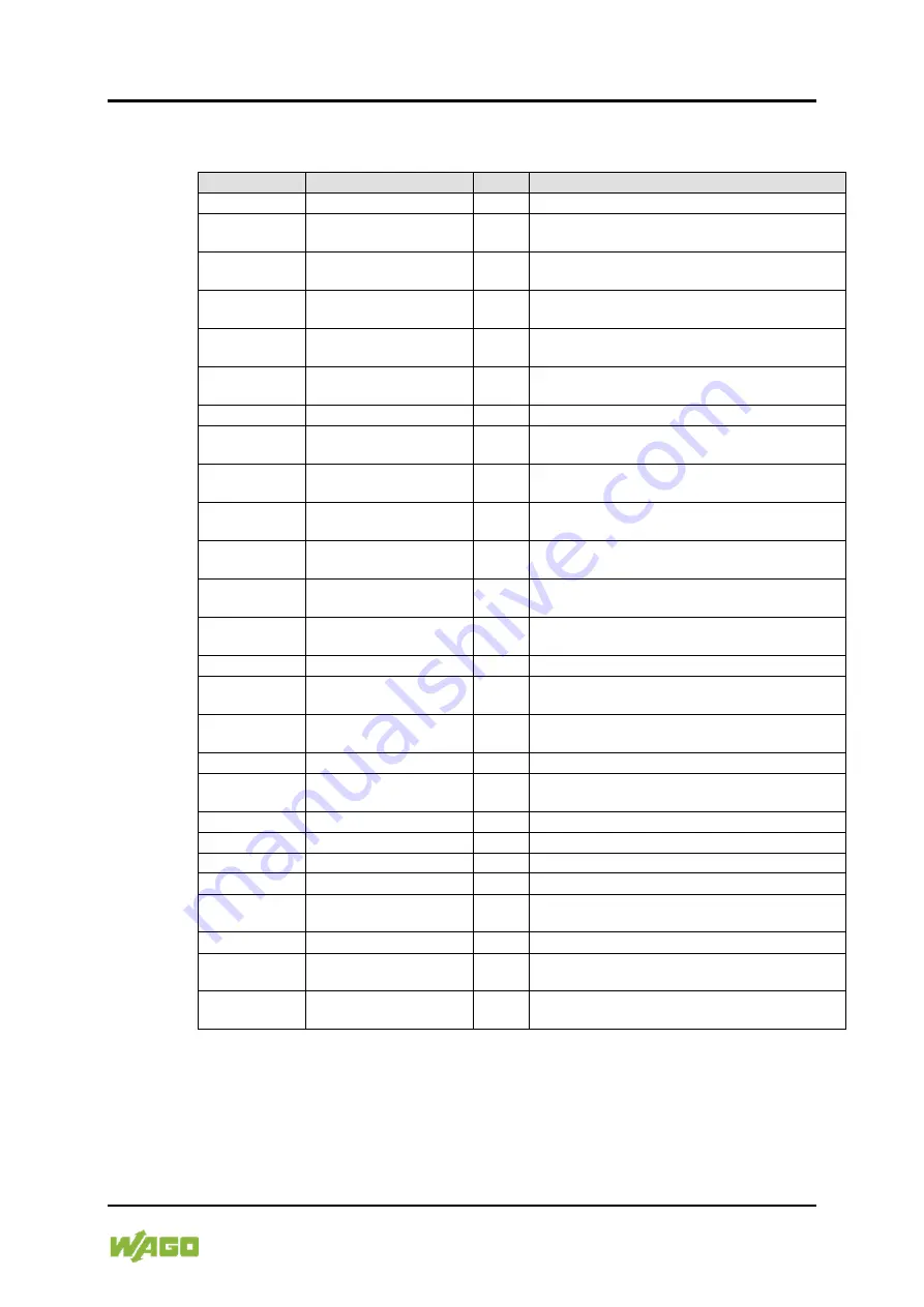
14.1.5 ICMP Group
Table 206: MIB II – ICMP Group
Identifier
Entry
Access Description
1.3.6.1.2.1.5.1 icmpInMsgs
R
Number of received ICMP messages
1.3.6.1.2.1.5.2 icmpInErrors
R
Number of received ICMP errors containing
ICMP-specific errors
1.3.6.1.2.1.5.3 icmpInDestUnreachs
R
Number of received ICMP destination
unreachable messages
1.3.6.1.2.1.5.4 icmpInTimeExcds
R
Number of received ICMP time exceeded
messages
1.3.6.1.2.1.5.5 icmpInParmProbs
R
Number of received ICMP parameter problem
messages
1.3.6.1.2.1.5.6 icmpInSrcQuenchs
R
Number of received ICMP source quench
messages
1.3.6.1.2.1.5.7 icmpInRedirects
R
Number of received ICMP redirect messages
1.3.6.1.2.1.5.8 icmpInEchos
R
Number of received ICMP echo request
messages (Ping)
1.3.6.1.2.1.5.9 icmpInEchoReps
R
Number of received ICMP echo reply messages
(Ping)
1.3.6.1.2.1.5.10 icmpInTimestamps
R
Number of received ICMP timestamp request
messages
1.3.6.1.2.1.5.11 icmpInTimestampReps
R
Number of received ICMP timestamp reply
messages
1.3.6.1.2.1.5.12 icmpInAddrMasks
R
Number of received ICMP address mask request
messages
1.3.6.1.2.1.5.13 icmpInAddrMaskReps
R
Number of received ICMP address mask reply
messages
1.3.6.1.2.1.5.14 icmpOutMsgs
R
Number of sent ICMP messages
1.3.6.1.2.1.5.15 icmpOutErrors
R
Number of sent ICMP messages that could not
be sent due to errors
1.3.6.1.2.1.5.16 icmpOutDestUnreachs
R
Number of sent ICMP destination unreachable
messages
1.3.6.1.2.1.5.17 icmpOutTimeExcds
R
Number of sent ICMP time exceeded messages
1.3.6.1.2.1.5.18 icmpOutParmProbs
R
Number of sent ICMP parameter problem
messages
1.3.6.1.2.1.5.19 icmpOutSrcQuenchs
R
Number of sent ICMP source quench messages
1.3.6.1.2.1.5.20 icmpOutRedirects
R
Number of sent ICMP redirection messages
1.3.6.1.2.1.5.21 icmpOutEchos
R
Number of sent ICMP echo request messages
1.3.6.1.2.1.5.22 icmpOutEchoReps
R
Number of sent ICMP echo reply messages
1.3.6.1.2.1.5.23 icmpOutTimestamps
R
Number of sent ICMP timestamp request
messages
1.3.6.1.2.1.5.24 icmpOutTimestampReps
R
Number of sent ICMP timestamp reply messages
1.3.6.1.2.1.5.25 icmpOutAddrMasks
R
Number of sent ICMP address mask request
messages
1.3.6.1.2.1.5.26 icmpOutAddrMaskReps
R
Number of sent ICMP address mask reply
messages


