background image

M.Y.2004 ed.01/03

Pag. 

16

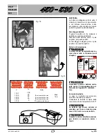
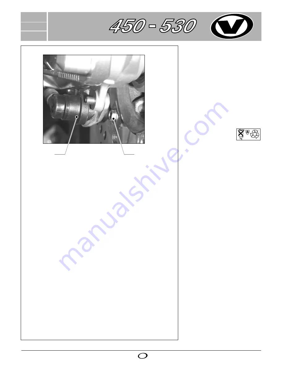
REGOLAZIONE DEL SENSORE 
MAGNETICO

Onde evitare malfunzionamenti del 
tachimetro, la distanza tra magnete 
(2) e sensore (1) deve essere: 
1.8 

÷

 2 mm. (fig.7)

BATTERIE

1 x 1,5 Volt, Tipo SR 44.
Sostituire le batterie dopo circa due 
anni e appena il display si offusca.

Le batterie possono 
essere restituite dopo 
l'uso.

Fig. 7

2

1

EN-E

EN-MAR

MX

1

Summary of Contents for 450

Page 1: ...MANUALE PER L UTENTE OWNER S MANUAL GEBRAUCHSANWEISUNGEN INSTRUCTION D EMPLOY EN E EN MAR MX M Y 2004 ed 01 03 ...

Page 2: ...1 M Y 2004 ed 01 03 Pag 00 ...

Page 3: ...e ein Kenner der sich nur mit dem Besten zufrieden gibt In ihrer VOR Motori stecken langjährige Er fahrungen aus dem Rennsport Wir haben sie für höchste Ansprüche in bezug auf Leistung Zuverlässigkeit und Sicherheit konstruiert und gebaut In dieser Betriebsanleitung finden Sie kurz und übersichtlich alles Wissenswerte für die Hand habung Wartung und Pflege Ihrer VOR Motori Folgen Sie den Anweisung...

Page 4: ...dule 85 1 3 Electrical circuite 91 CHAPTER 2 Spare parts catalogue Ric 4 CHAPTER 3 Tool Kit Att 3 SOMMAIRE CHAPITRE 1 Conditions de garantie 3 La sécurité 4 Vérification du fonctionnement 6 Numéros d intefication 10 Commandes 10 Préparation à la mise en marche 19 Mise en marce 19 Entretien 20 Interventions techniques 38 Fiche techniche 70 1 1 Couples de serrage 77 1 2 Programme de maintenance 85 1...

Page 5: ... TERMS OF WARRANTY Read the instructions quoted in the owner s manual ANWEISUNGEN FÜR DIE GARANTIE Dazu sind die Anweisungen im Handbuch aufmerksam zu lesen PRESCRIPTIONS DE GARANTIE Lire les dispositions contenues dans le manuel spécifique EN E EN MAR MX 1 1 M Y 2004 ed 01 03 Pag 3 ...

Page 6: ...rante olio o liquido refrigerante Eseguire un saldo ancoraggio con corde o funi Chiudere i rubinetti del carburante SAFETY Protective clothing Wear suitable clothing when using the bike Wear helmet jacket gloves and boots also for short rides Always turn low beam headlights on during a ride so that other road users may see you in time Never drive after drinking alcohol after taking medicines or dr...

Page 7: ...Sie die Kraftstoffhähne SECURITE Vêtements de protection Pour utiliser le motocycle il est nécessaire de porter des vêtements appropriés Toujours porter le casque le blouson les gants et les bottes même pour de courts trajets Toujours allumer les feux de croisement pendant la marche afin que les autres utilisateurs de la route puissent vous voir à temps Ne jamais conduire après avoir consommé des ...

Page 8: ...cio il filo e la candela siano integri Verificare il buon funzionamento del motore In caso contrario rivolgersi ad un officina specializzata VOR Pulire o sostituire se necessario Controllare il funzionamento e la regolazione del cavo Ogni 100 ore sostituire la valvola gas lo spillo conico ed il getto a spillo In caso di malfunzionamento del motore provvedere alla sua regolazione Controllare il liv...

Page 9: ...ded fuel Make sure that the oil level is close to the full mark when the bike is on the stand Check that cap wire and sparking plug are intact Check that the engine is in good working order If not contact a VOR specialized shop Clean or replace if necessary Check the cable operation and adjustment Every 100 hours replace gas valve conical needle and needle nozzle Adjust the engine in case of failu...

Page 10: ...teht Kontrollieren dass der Zündkerzenstecker der Draht und die Kerze unbeschädigt sind Prüfen ob der Motor störungsfrei funktioniert Andernfalls wenden Sie sich an eine VOR Fachwerkstatt Reinigen oder wenn nötig ersetzen Funktionsweise und Einstellung des Kabels kontrollieren Alle 100 Stunden das Gasventil die konische Nadel und die Nadeldüse ersetzen Bei Funktionsstörungen den Motor regulieren D...

Page 11: ... du cache du fil et de la bougie Vérifier le fonctionnement correct du moteur Le cas échéant s adresser à un atelier spécialisé VOR Nettoyer ou remplacer si besoin en est Contrôler le fonctionnement et le réglage du câble Remplacer la soupape du gaz le pointeau conique et le jet à pointeau toutes les 100 heures En cas de dysfonctionnement du moteur procéder à son réglage Contrôler le niveau du liq...

Page 12: ...riportato il n di telaio Su lato SX del carter motore é posizionato il numero di serie del motore COMANDI 1 Tappo serbatoio carburante 2 Fanale posteriore 3 Fanale anteriore 4 Pedale comando freno posteriore 5 Rubinetto carburante 6 Pedale avviamento 7 Pedale comando cambio 4 6 1 2 3 5 7 EN E EN MAR MX Fig 1 1 ...

Page 13: ...ich links am Motorgehäuse FAHREN Bedienungsorgane 1 Tankdeckel 2 Rücklicht 3 Kurzschlussschalter 4 Fernlicht an 5 Abblendlicht an 6 Lichtschalter Pos ON 7 Blinklichtschalter NUMÉROS D IDENTIFICATION La plaquette indiquant le numéro de châssis est positionnée sous le convoyeur droit Le numéro de série du moteur se trouve sur le côté gauche du carter moteur CONDUITE Commandes 1 Bouchon de réservoir ...

Page 14: ...erde si illumina a lampeggiatore inserito F Spia di controllo blu si illumina quando è accesa la luce abbagliante G Spia di controllo verde si illumina quando è accesa la luce anabbagliante 18 Leva comando freno anteriore 19 Comando acceleratore 20 Interruttore di corto circuito Con la vite di regolazione 21 può essere variata la posizione base della leva frizione La leva viene utilizzata quando d...

Page 15: ...s F Die blaue Kontrollampe leuchtet wenn das Fernlicht eingeschalter ist G Die grüne Kontrollampe leuchtet wenn das Abblendlicht eingeschalter ist 18 Vorderradbremsgriff 19 Gasdrehgriff 20 Kurschlußtaster Mit der Einstellschraube 21 kann die Grundstellung des Kupplungshebels verändert werden Der Handdekompressorhebel wird nur benötigt wenn nach einem Sturz der Vergaser übergelaufen ist Zum Freipum...

Page 16: ...mo impulso proveniente sempre dal sensore velocità Il dato non viene memorizzato in modo permanente E possibile azzerare il contatore legato a questo parametro premendo in corrispondenza della funzione LAP il pulsante per circa 3 sec sino a quando non compare il valore 00 00 EN E EN MAR MX L azzeramento di LAP possibile sia a veicolo fermo che in movimento produce anche l azzeramento di TD Se il d...

Page 17: ...ng the last impulse from that same speed sensor This data is not memorised permanently The counter connected to this parameter can be reset by pressing the pushbutton by the LAP function for about 3 seconds until the value 000 0 appears Resetting the LAP which can done both while the vehicle is moving or stopped also resets the TD If the data is higher than the number 23 59 meaning 23h59 59 the sy...

Page 18: ...mit dem ersten Impuls des Geschwindigkeitssensors aktiviert und 3 Sekunden nach dem Empfang des letzten Impulses des Geschwindigkeitssensors wieder deaktiviert Der Wert wird nicht kontinuierlich gespeichert EN E EN MAR MX Der Zähler für diesen Parameter kann auf Null gesetzt werden indem die der Funktion LAP entsprechende Taste 3 Sekunden lang gedrückt wird bis der Wert 00 00 erscheint Die Nullste...

Page 19: ...jours en provenance du détecteur de vitesse La donnée n est pas mémorisée de façon permanente Il est possible de remettre à zéro le compteur lié à ce paramètre en appuyant au niveau de la fonction LAP sur le bouton pendant environ 3 s jusqu à ce que la valeur 00 00 apparaisse EN E EN MAR MX La remise à zéro de LAP possible sur un véhicule tant à l arrêt qu en mouvement entraîne également la remise...

Page 20: ...funzionamenti del tachimetro la distanza tra magnete 2 e sensore 1 deve essere 1 8 2 mm fig 7 BATTERIE 1 x 1 5 Volt Tipo SR 44 Sostituire le batterie dopo circa due anni e appena il display si offusca Le batterie possono essere restituite dopo l uso Fig 7 2 1 EN E EN MAR MX 1 ...

Page 21: ...Magneten 2 und dem Sensor 1 1 8 2 mm betragen Siehe Abb 7 BATTERIEN 1 x 1 5 Volt Typ SR 44 Die Batterien nach ca zwei Jahren ersetzen bzw sobald der Display sich verdunkelt Die Batterien können nach dem Gebrauch zurückgegeben werden REGLAGE DU CAPTEUR MAGNETIQUE Afin d éviter les dysfonctionnements du tachymètre la distance entre l aimant 2 et le capteur 1 doit être de 1 8 2 mm fig 7 BATTERIES 1 x...

Page 22: ...e scaricare la batteria ricorrere alla procedura di avviamento a pedale Problemi di avviamento Nel caso la motocicletta rimanga inutilizzata per un lungo periodo si consiglia per agevolare l avviamento di utilizzare la leva del decompressore manuale posta sul lato sinistro del manubrio Avviamento a pedale 1 Ricordarsi che un motore a 4 tempi necessita di 2 giri dell albero motore per un ciclo comp...

Page 23: ...as immédiatement ne pas insister mais répéter la procédure en actionnant légèrement la manette du gaz Si le moteur ne démarre toujours pas il est préférable de faire appel à la procédure de démarrage par pédale plutôt que de décharger la batterie Problémes de démarrege Dans le cas la motocyclette reste inutilisée pour une longue période se conseillé pour faciliter le démarrage d utiliser le levier...

Page 24: ...i la motocicletta è in condizioni di potere essere usata liberamente Partenza Tirare la leva della frizione ed inserire la 1 marcia poi lasciare lentamente la leva accelerando contemporaneamente Se le condizioni del traffico e quelle del terreno lo permettono raggiunto il n di giri idoneo innestare uno alla volta i rapporti superiori Per fare questo chiudere il comando dell acceleratore tirare la ...

Page 25: ...eitig beschleunigen Wenn die Verkehrs und Straßenbedingungen es zulassen beim Erreichen der geeigneten Drehzahl nach und nach die höheren Gänge einlegen Dazu die Schaltung des Beschleunigers beenden den Kupplungshebel ziehen und gleichzeitig den nächsthöheren Gang einlegen den Kupplungshebel lösen und beschleunigen WARTUNG Kontrolle des Motorölstandes Der Motorölstand muss bei warmem Motor kontrol...

Page 26: ... le viti D e C far defluire l olio in un recipiente Pulire accuratamente le superfici di tenuta e le viti precedentemente tolte attendere che l olio sia completamente defluito e rimontare le viti D e C Togliere il tappo A dal coperchio frizione e riempire d olio fino al livello indicato in figura 13 Rimontare il tappo A AVVERTENZA Si consiglia di effettuare la sostituzione dell olio motore più fre...

Page 27: ...entfernten Schrauben sorgfältig säubern warten dass das Öl vollständig abgeflossen ist und die Schrauben D und C wieder festziehen Den Verschluss A vom Kupplungsdeckel abnehmen bis der in der Abbildung 13 gezeigte Stand erreicht ist dann den Verschluss A wieder aufsetzen HINWEIS Es wird angeraten das Motoröl öfter alle 8 Stunden während der ersten Zeit der Nutzung des Fahrzeugs zu wechseln Vidange...

Page 28: ...retto funzionamento del cavo di accensione e della candela 3 Se necessario sostituirla Candela consigliata NGK CR8 EK Distanza tra gli elettrodi 0 6 mm Coppia di serraggio candela 15 Nm ATTENZIONE Sostituire le candele d accensione con altre di grado termico diffe rente può comportare gravi danni al motore Fig 17 Fig 16 EN E EN MAR MX 1 ...

Page 29: ... Vérifier le fonctionnement correct du câble d allumage et de la bougie 3 La remplacer si besoin en est Bougie recommandée NGK CR8 EK Ecartement des électrodes 0 6 mm Couple de serrage 1 5 Kg m 15 Nm AVERTISSEMENT Le fait de modifier incorrectement le degré thermique de la bougie d allumage risque d endommager le moteur Spark plugs 1 Disconnect the HT lead and use the appropriate box spanner to re...

Page 30: ... richiede manutenzione l unico accorgimento utile consiste nel tenere pulite e ingrassati i poli della batteria Smontaggio batteria Togliere le quattro viti A sollevare il parafango asportare la batteria Staccare dalla batteria prima il polo negativo poi quello positivo Al rimontaggio collegare prima il polo positivo e poi quello negativo Metodo di riempimento ATTENZIONE Al momento del riempimento...

Page 31: ...st undurchlässig und erfordert keine Wartung Als einzige nützliche Maßnahme sollte darauf geachtet werden dass die Batteriepole stets sauber und gefettet sind Ausbau der Batterie Die vier Schrauben A entfernen und den Kotflügel anheben Die Batterie entnehmen Erst den negativen dann den positiven Pol von der Batterie abtrennen Beim Wiedereinbauen erst den positiven dann den negativen Pol anschließe...

Page 32: ...rovocando un anomala usura del pistone e del cilindro Radiatore Verificare che a motore freddo il liquido di raffreddamento superi la massa radiante Nel caso venisse svuotato il circuito provvedere allo spurgo aria Usare prodotti di buona qualità per evitare la formazione di emulsioni e l insorgere di corrosione ATTENZIONE Pericolo di ustioni Intervenire solo a motore freddo In caso di ustioni sci...

Page 33: ...ie Kühlflüssigkeit bei kaltem Motor den Kühlerblock übersteigt Falls der Kreis entleert wird muss auch eine Entlüftung vorgenommen werden Produkte guter Qualität verwenden damit sich keine Emulsionen bilden und keine Korrosion auftritt ACHTUNG Verbrennungsgefahr Nur bei kaltem Motor arbeiten Bei Verbrennungen sofort mit kaltem Wasser spülen und einen Arzt aufsuchen ACHTUNG Falls der Stöpsel A des ...

Page 34: ...a posteriore ed i controdadi dei registri destro e sinistro Agire sulle vi ti di regolazione B curando l allinea mento della ruota aiutarsi con le tacche di riferimento Serrare i controdadi dei registri Serrare il dado del perno ruota po steriore Manutenzione della catena La catena va lavata con abbondante acqua senza l uso di spazzole e solventi Una volta asciutta lubrificar la con un prodotto de...

Page 35: ... the right and left adjuster lock nuts Turn the adjusting screws B using the wheel alignment refer to the reference marks Tighten the register lock nuts Tighten the rear wheel pin nut Chain maintenance The chain must be washed with abundant water without using brushes or solvents Once dry lubricate it using a mild product WARNING Once you have reached the stroke adjustment limit replace chain rim ...

Page 36: ...cedura 1 Posizionare la moto sul supporto Fig 24 2 Allentare il dado A Fig 25 sul perno ruota 3 Allentare le due viti B Fig 26 sul lato sinistro 4 Allentare le viti C Fig 27 sul lato destro 5 Estrarre il perno D dalla ruota 6 Togliere la ruota dalla sua sede Montaggio ruota anteriore 1 Prima di rimontare la ruota ante riore ingrassare il perno ruota 2 Inserire la ruota dopo aver veri ficato che i ...

Page 37: ...nterior wheel proceeding how it follows 1 Place the bike on the stand Fig 24 2 Remove the nut A Fig 25 from the wheel shaft 3 Remove the nuts B Fig 26 from the left side 4 Remove the nuts C Fig 27 from the right side 5 Remove pin D from the wheel 6 Remove the wheel from its housing Fitting the front wheel 1 Before reinstalling the front wheel lubricate the wheel shaft 2 Check that the spacers have...

Page 38: ...are quelle nuove Fare attenzione affinchè il montaggio sia corretto Controllare il funzionamento del freno con la ruota montata facendo girare la ruota stessa Per raggiungere la massima efficienza di frenatura si consiglia di seguire un periodo di rodaggio per le pastiglie ATTENZIONE Il liquido dei freni può essere peri coloso per uomini e animali E mol to nocivo o mortale in caso di inge stione E...

Page 39: ...bed under the heading Front wheel Then begin by separating the brake pads B Fig 29 as far apart as possible Remove the split D the pin C Fig 29 and remove the pads Fit new pads Take care to fit the new pads correctly After fitting the wheel spin it and check the performance of the brake To achieve the best possible brake performance run the pads in gently and carefully WARNING Liquid of brakes can...

Page 40: ...olio si trovi sempre tra il segno di minimo e massimo del serbatoio C Fig 31 del freno posteriore Rabboccare se necessario olio Dot 4 o 5 2 Per la regolazione del gioco e della distanza del pedale dalla pedana poggiapiedi agire sul registro D 3 Per raggiungere le pastiglie dei freni smontare dapprima la ruota po steriore vedi capitolo Ruota poste riore Allontanare poi le pastiglie C Fig 32 il più ...

Page 41: ...flüssigkeit DOT 4 oder 5 nachfüllen 2 Für die Einstellung des Spiels und der Höhe des Pedals von der Pedalschaltung betätigt man Einstellschraube D 3 Zum Aus Einbau der Bremsbeläge muss zunächst das Hinterrad ausgebaut werden s Abschnitt Hinterrad Danach die beiden Bremsbeläge C Abb 32 möglichst weit auseinanderdrücken Den Kranz F und den Bremsbolzen E Abb 32 herausnehmen Neue Bremsbeläge einbauen...

Page 42: ...la Girando quest ultima in senso orario la quantità di carburante diminuisce miscela povera girando in senso antiorario la quantità di carburante aumenta miscela ricca La regolazione del minimo va fatta nel seguente modo 1 A motore caldo avvitare comple tamente la vite B per poi svitarla fino ad ottenere la regolazione base prevista da Vor vedi dati tecnici carburatore 2 Agendo sulla vite A regola...

Page 43: ...educes the quantity of fuel pour carburation or turning in the direct anticlockwise the quantity of fuel increases rick carburation Idle adjustment must be carried out as follows 1 With hot engine tighten screw A thoroughly and then unscrew it to obtain the base adjustment as provided by Vor see carburettor technical data 2 Turn screw A to adjust the idle to about 1400 1500 rpm 3 Tighten and loose...

Page 44: ...telaio A e serbatoio fianchetti laterali anteriori B Fig 35 Estrarre il perno centrale C e le viti D che uniscono il telaietto posteriore al telaio Fig 35 36 Chiudere il rubinetto del carburante e togliere il tubetto G Fig 36 Sconnettere il cablaggio elettrico E Fig 35 Allentare la fascetta di innesto del manicotto sulla scatola filtro aria F Fig 37 Sollevare il complessivo in oggetto Fig 38 Fig 3...

Page 45: ...ructions Remove the seat Remove the tank frame fixing screw A and the tank front side panel screw B Fig 35 Remove the central pin C and screws D that connect the small rear frame to the frame Fig 35 36 Close the fuel cock and remove pipe G Fig 36 Disconnect wiring E Fig 35 Loosen the coupling engagement clamp on the air filter box aria F Fig 37 Lift the assembly Fig 38 Dépose totale réservoir sell...

Page 46: ... albero 3 Inserire la rondella di rame e bloccare il tutto con la coppiglia 6 Regolazione decompressore 1 Posizionare il pistone al P M S pun to morto superiore mediante compara tore C Fig 40 2 Misurare con spessimetro il gioco tra il bilancere e la parte piana del l alberino decompressore con valvole chiuse il valore corretto è di 0 4 mm 3 Se necessario procedere alla rego lazione con il registro...

Page 47: ...r washer and lock with the split pin Decompression adjustment 1 To place the piston on the P M S by means of comparator C Fig 40 2 Measuring with thickness gauge the gap between the equalizer and the plain part of the decompression shaft with closed valves correct value is 0 4 mm 3 If necessary proceede to adjust ment with the regulator at thread B Fig 40 Montage de l arbre du décompresseur Procéd...

Page 48: ...amento fun zioni correttamente è importante che l automatismo di decompressione fun zioni correttamente ogni volta L albe rino dell alzavalvole e il filo devono es sere mantenuti puliti e lubrificati Per verificare il corretto funzionamen to dell automatismo di decompressio ne procedere come segue 1 Portare il pistone al P M S ATTENZIONE Le valvole devono essere chiuse e i bilanceri liberi 2 Utili...

Page 49: ...line Automatic decompression The kick starter will operate correctly only if automatic decompression co mes into operation every time the kick starter is kicked down The valve lifter shaft and wire must be kept clean and lubricated To verify the correct function of sy stem of decompression proceeding how it follows taking piston to the P M S WARNING Valves have to be closed and free rocket arms Ut...

Page 50: ...cessitasse di qualche intervento procedere come segue 1 Rimuovere il coperchio per accedere al sistema di accensione 2 Bloccare il volano con l attrezzo di ritegno B Svitare il dado al centro girandolo in senso orario 3 Applicare l estrattore C al centro del volano e allentare quest ultimo Fig 43 Fig 42 Fig 44 B C EN E EN MAR MX MX 1 M Y 2004 ed 01 03 Pag 46 ...

Page 51: ...ndet ein elektronisch Das Zündsystem erfordert keine gewöhnlichen Wartungsarbeiten aber falls ein Eingriff erforderlich sein sollte wie folgt vorgehen 1 Das Gehäuse entfernen 2 Das Schwungrad mit dem Werkzeug B blockieren 3 Den Auszieher C an der Antriebswelle ansetzen und das Schwungrad herausziehen CROSS ignition system The ignition system used is electronic The ignition system does not require ...

Page 52: ...ne deve essere sceso di 8 mm dal P M S tale controllo avviene leggendo il comparatore 5 Sfilare il rotore 2 dalla propria sede Fig 23 6 Serrare le 3 viti 3 Fig 47 di bloc caggio dello statore 4 utilizzando del la Loctite frenafiletti di Tipo medio 243 7 Riposizionare il rotore facilitandone l ingresso con un colpettino di martello in plastica 8 Riposizionare l estrattore 4 come in fig 48 e serrare...

Page 53: ...rt Fig 46 rotate counterclockwise the rotor until that inserted pin goes at bottom position of alignment between rotor and stator In such position the piston has to descend of 8 mm from the P M S check reading the comparator 5 Unthreading the rotor 2 from its own position Fig 45 6 Tighten the 3 screws 3 Fig 47 of to block of stator 4 utilizing Loctite of middle type 243 7 Reinstall the rotor facil...

Page 54: ...g 50 3 Applicare l estrattore C all albero motore ed estrarre il volano Fig 51 NOTA Se si dovesse incontrare difficoltà nell estrazione del volano riscaldare il mozzo mediante un phon proteggendo i magneti con l apposito attrezzo cod 100040010 D come rappresentato in fig n 51A In fase di rimontaggio sgrassare il cono albero motore e sede rotore volano poi fare coincidere la tacca di riferimento de...

Page 55: ...ren und die Mutter in der Mitte im Uhrzeigersinn abschrauben Abb 50 3 Den Auszieher C an der Antriebswelle ansetzen und das Schwungrad herausziehen Abb 51 HINWEIS Sollte man bei der Abnahme des Schwungrads auf Schwierigkeiten stoßen sollten sie die Nabe mit Hilfe eines Föhn erwärmen dabei die Magneten dem dafür vorgesehenen Werkzeug Cod 100040010 schützen D wie in Fig Nr 51A dargestellt Beim Wiede...

Page 56: ...re in sede la gabbia a rulli 3 avendo l avvertenza di lubrificarla con olio prima del montaggio 3 Infilare la campana 4 nel verso in dicato in fig 53 dentatura all interno 4 In sequenza montare la ranella 5 il tamburo frizione 6 la rondella 7 e il dado 8 Fig 53 Fig 54 1 2 5 4 3 6 7 8 EN E EN MAR MX 1 M Y 2004 ed 01 03 Pag 52 ...

Page 57: ...igure 2 To install in seat the bearing at rollers 3 then to lubricate with oil before of assembly 3 To install the clutch housing 4 in to direction indicated in fig 53 the gear teeth on the inside 4 Fit washer 5 clutch drum 6 washer 7 and nut 8 in sequence Montage embrayage 1 Engager la rondelle 1 dans le sens illustré dans la figure et l entretoise 2 sur l arbre primaire 2 Placer la cage à roulea...

Page 58: ...ischi frizione 12 come in Fig 56 8 dischi metallici 7 dischi guarniti 7 All interno del piatto spingidisco posizionare il cuscinetto assiale ed il rasamento 8 Montare il piatto spingidisco con relative molle scodellini e viti fig 57 ATTENZIONE Fare coincidere la freccia ricavata sul piatto spingidisco con la tacca di riferimento sul tamburo M Y 2004 ed 01 03 Pag 54 ...

Page 59: ...latte das Achslager und die Ausgleichscheibe anordnen 8 Die Druckplatte mit den entsprechenden Federn Ventilfedertellern und Schrauben montieren Abb 57 ACHTUNG Der Pfeil auf der Druckplatte muss an der Bezugskerbe auf der Trommel ausgerichtet werden 5 Monter la tige d embrayage 9 la bille Ø 8 10 et le plateau de débrayage 11 fig 55 6 Introduire les disques d embrayage 12 comme illustré dans la Fig...

Page 60: ...8 2 Posizionare nell ordine i rasamenti l ingranaggio il perno e la gabbia a rulli Fig 59 3 Dopo aver fasato anche la dentatura del terzo ingranaggio C di distribuzione posizionare nell ordine i rasamenti il perno l ingranaggio la gabbia a rulli e il distanziale Fig 61 4 Montare l ingranaggio sull albero a camme in modo da avere i due fori filettati disposti orizzontalmente e la spina verticalment...

Page 61: ... 58 2 Insert shims gear pin and roller retainer Fig 59 in sequence 3 Proceed with timing of third timing gear C and then fit shims gear pin roller retainer and spacer Fig 61 in the order indicated 4 Fit the gear on the camshaft orienting the two threaded holes horizontally and the plug vertically Fig 60 Réglage du calage de distribution 1 A l aide de la clé A spécialement prévue à cet effet aligne...

Page 62: ...tare un comparatore nel foro della candela e portare il pistone al P M S 7 Pulire accuratamente il cono del l albero motore 8 Montare l ingranaggio sull albero motore aiutandosi con un martello in gomma per facilitarne l ingresso 9 Inserire l attrezzo dentato per evi tare la rotazione del motore Montare e serrare il dado dopo avere posto della loctite 243 sul filetto Fig 65 10 Montare le boccole d...

Page 63: ...en Konus der Antriebswelle sorgfältig säubern 8 Das Getriebe auf die Antriebswelle montieren Ein Gummihammer erleichtert das Einsetzen 9 Die gezahnte Vorrichtung einsetzen um die Motordrehung zu vermeiden Loctite 243 auf das Gewinde der Mutter auftragen dann diese einbauen und anziehen Abb 65 10 Die Zentrierbuchsen einbauen die Auflageflächen säubern Loctite 5699 auftragen und das Gehäuse befestig...

Page 64: ...riore per evitare che l abbassamento delle valvole causi il danneggiamento delle stesse contro il pistone S mm 1 2 1 25 1 3 1 35 1 4 1 45 1 5 1 55 1 6 1 65 1 7 1 75 1 8 1 85 1 9 1 95 2 2 05 2 1 2 15 2 2 2 3 2 35 2 4 2 45 2 5 Cod 505218120 505218125 505218130 505218135 505218140 505218145 505218150 505218155 505218160 505218165 505218170 505218175 505218180 505218185 505218190 505218195 505218200 5...

Page 65: ...benen Werten entspricht müssen die kalibrierten Pastillen durch andere in geeigneter Dicke ersetzt werden Beim Austausch muss sich der Kolben in der Nähe des unteren Totpunkts befinden um zu vermeiden dass die Ventile beim Absenken gegen den Kolben beschädigt werden Beispiel von Bestellung Pastillen Dicke 1 3 mm Cod 505218130 REGLAGE DU JEU DES SOUPAPES Le jeu des soupapes doit être égal à 0 1 mm ...

Page 66: ...olte Misurare nuovamente la distanza 1 che deve risultare 25 30 mm infe riore rispetto alla prima misurazione NOTA Questa misurazione va effettuata a moto scarica senza pilota La misurazione effettuata invece con il pilota e con entrambe le ruote a terra dovrà essere 50 60 mm in meno rispetto alla misura effettuata con la motocicletta su di una pedana con la ruota anteriore sollevata da terra Qual...

Page 67: ... down the front fork a few times Measure the distance 1 again The distance should now be 25 30 mm less than during the first measu rement NOTE No one should be seated on the mo torcycle The measurement effected instead with pilot and with both wheels at earth will have to give 50 60 mm in less respectto effected measure with motorcycle on a dais with front wheel risen by earth In case measures tak...

Page 68: ...one standard dalla posizione tutta avvitata ruotare la vite di 18 scatti Ammortizzamento in compressione della forcella anteriore Fig 68 Il freno idraulico di compressione gestisce il comportamento in fase di compressione della forcella Esso può essere regolato con le viti di regolazione poste sull estremità inferiore dei gambali Ruotando in senso orario aumenta la capacità di ammortizzamento ment...

Page 69: ...steps Front fork compression damping Fig 68 The hydraulic compression brake manages behavior during fork compression It can be regulated through the adjusting screws located on the lower end of the fork The damping capacity can be increased through clockwise rotation and decreased through counter clockwise rotation Standard setting from the thoroughly tightened position rotate the screw by 12 step...

Page 70: ...ione 24 Regolazione sospensione posteriore 1 Misurare la distanza D Fig 69 da terra con la motocicletta senza con ducente in sella posta su uno sga bello e con gli ammortizzatori estesi come indicato dalla figura 2 Rimuovere lo sgabello e caricare la moto con il conducente in sella che deve tenere entrambi i piedi sulle due pedane poggiapiedi Misurare la distanza E Fig 70 che deve essere ora 90 10...

Page 71: ...ch 24 Rear suspension adjustment 1 Measure the distance D Fig 69 when the motorcycle is supported on a stand so that the shock absorbers are fully extended as shown in the figure 2 Remove the stand and sit in the seat with both feet resting on the footrests Measure distance E Fig 70 which should now be 90 100 mm less than D Fig 69 If distance does not match adjust the spring pre charge by means of...

Page 72: ...e viti 1 Ruotando in senso orario si aumenta la capacità di ammortizzamento mentre ruotando in senso antiorario si diminuisce Ammortizzamento in estensione dell ammortizzatore posteriore 2 Pomello regolazione estensione Ruotando in senso orario si aumenta la capacità di ammortizzamento mentre ruotando in senso antiorario si diminuisce EN E EN MAR MX OHILNS 1 2 Fig 73 1 ...

Page 73: ...clockwise rotation and decreased through counter clockwise rotation Rear shock absorber extension damping 2 Extension adjusting knob The damping capacity can be increased through clockwise rotation and decreased through counter clockwise rotation Amortissement en compression de l amortisseur arrière Le degré d amortissement en compression peut être géré en agissant sur la vis 1 2 Tourner cette vis...

Page 74: ...lte velocità Disco Ø 270 mm e pinza Brembo a 2 pistoncini Disco Ø 220 mm e pinza Brembo a 1 pistoncino 90 90 x 21 140 80 x 18 360 mm 930 mm 2160 mm 1485 mm 122 Kg 9 lt 1 350 lt a motore nuovo aperto e lavato 1 250 lt sostituzione EN E 530 450 EN MAR 530 450 MX 530 450 97x71 mm 97x60 1 mm Asp 0 10 Scarico 0 15 524 67 cc 444 cc 11 5 1 12 1 KEIHIN FCR 39 28 5 Kg primaria 29 78 finale 14 48 530 finale...

Page 75: ...ne cylinder Brembo caliper 90 90 x 21 140 80 x 18 360 mm 930 mm 2160 mm 1485 mm 122 Kg 9 lt 1 350 lt new engine dismounted and washed 1 250 lt substitution EN E 530 450 EN MAR 530 450 MX 530 450 97x71 mm 97x60 1 mm Intake 0 10 Exhaust 0 15 524 67 cc 444 cc 11 5 1 12 1 KEIHIN FCR 39 28 5 Kg primary 29 78 final 14 48 530 final 13 50 450 Hydraulic wet multi plate Removable five speed 1ª 15 32 2ª 18 2...

Page 76: ...Bremszange Brembo Scheibenbremse Ø 220 mm Einkolben Bremszange Brembo 90 90 x 21 140 80 x 18 360 mm 930 mm 2160 mm 1485 mm 122 Kg 9 lt 1 350 bei neuem Motor offen und gewaschen 1 250 lt beim Ölwechsel EN E 530 450 EN MAR 530 450 MX 530 450 97x71 mm 97x60 1 mm Einlaß 0 10 Auslaß 0 15 524 67 cc 444 cc 11 5 1 12 1 KEIHIN FCR 39 28 5 Kg primärtrieb 29 78 finale 14 48 530 finale 13 50 450 Ölbad Scheibe...

Page 77: ...rier Brembo a 2 pistons Arriere a disque Ø 220 mm et etrier Brembo a 1 piston 90 90 x 21 140 80 x 18 360 mm 930 mm 2160 mm 1485 mm 122 Kg 9 lt 1 350 lt nouveau moteur ouvert et lavé 1 250 lt substitution EN E 530 450 EN MAR 530 450 MX 530 450 97x71 mm 97x60 1 mm Admiss 0 10 Échapp 0 15 524 67 cc 444 cc 11 5 1 12 1 KEIHIN FCR 39 28 5 Kg primaires 29 78 final 14 48 530 final 13 50 450 Multidisque a ...

Page 78: ...f API SG SH classes see table WARNING Insufficient or poor quality oil may cause an early engine wear MOTORÖL Nur Öl guter Qualität verwenden Es sollte mindestens den Qualitätsstandards der Klassen API SG SH entsprechen siehe Tabelle ACHTUNG Ungenügende Motorölmengen oder Öl geringer Qualität führen zu vorzeitigem Verschleiß des Motors HUILE DE MOTEUR Utiliser exclusivement une huile de bonne qual...

Page 79: ...HL FÜR DIE ÖFFNUNG DER LEERLAUFSCHRAUBE EINSPRITZDÜSE POTENTIOMETER KONISCHE NADEL Nr BEZUGSZEICHEN EN E 450 cc 530 cc EN MAR 450 cc 530 cc 175 50 85 200 100 1 1 2 Ø 0 35 0 5 0 68 V OBDTM TIPO TYPE FCR H 39 EN E 450 cc 530 cc EN MAR 450 cc 530 cc 175 50 85 200 100 1 1 2 Ø 0 35 0 5 0 68 V OBDTM M Y 2004 ed 01 03 Pag 75 MX 450 cc 530 cc 175 50 85 200 100 1 1 2 Ø 0 35 0 5 0 68 V OBDTM MX 450 cc 530 c...

Page 80: ...E ÖFFNUNG DER LEERLAUFSCHRAUBE EINSPRITZDÜSE POTENTIOMETER KONISCHE NADEL Nr BEZUGSZEICHEN OPTIONAL MX 530 cc 165 52 85 200 100 1 1 2 Ø 0 35 0 5 0 68 V OBDTM TIPO TYPE FCR H 41 OPTIONAL MX 530 cc 165 52 85 200 100 1 1 2 Ø 0 35 0 5 0 68 V OBDTM M Y 2004 ed 01 03 Pag 76 GETTO MASSIMO GETTO MINIMO GETTO AVVIAMENTO GETTO MASSIMO ARIA GETTO MINIMO ARIA N GIRI DI APERTURA VITE DEL MINIMO POLVERIZZATORE ...

Page 81: ...M Y 2004 ed 01 03 Pag 77 COPPIE DI SERRAGGIO TIGHTENING TORQUES ANZUGMOMENT COUPLES DE SERRAGE EN E EN MAR MX 1 1 1 ...

Page 82: ...plungsdeckel Deckel Zündung und Verteilung Vis carter couvercle embrayage Couvercle allumage et distribution Viti scarico olio Oil dump screws Ölablassschrauben Vis vidange huile Tappo filtro olio superiore Upper oil filter cap Verschluss Ölfilter oben Bouchon filtre à huile supérieur Tappo filtro olio inferiore Lower oil filter cap Verschluss Ölfilter unten Bouchon filtre à huile inférieur Vite t...

Page 83: ...iti coperchietti valvole Valve cover screws Schrauben Ventildeckel Vis couvercles soupapes Dado esagonale alb motore lato volano Crankshaft hex nut flywheel side Sechskantmutter Antriebswelle Schwungradseite Écrou six pans vilebrequin côté volant de moteur Dado tamburo interno frizione Inner clutch drum nut Mutter Kupplungstrommel innen Écrou tambour intérieur embrayage Viti molle frizione Clutch ...

Page 84: ... Electric starter motor screws Schrauben elektrischer Anlasser Vis démarreur électrique Raccordo tubo sfiato olio motore Engine oil breather pipe connection Anschlussstück Entlüftungsrohr Motoröl Raccord tuyau de mise à l air huile de moteur Vite pedale avviamento Starter pedal screw Schraube Startpedal Vis pédale de démarrage Vite leva cambio Gear lever screw Schraube Schalthebel Vi levier des vi...

Page 85: ...Zapfen erstes Verteilergetriebe Vis de fixation plaquette d étanchéité axe premier engrenage de distribution Grani di fermo perni dei bilancieri Rocker arm pin locking dowels Haltestifte der Kipphebelzapfen Ergots de retenue axes des culbuteurs Dado albero motore lato frizione Clutch side crankshaft nut Mutter Antriebswelle Kupplungsseite Ecrou vilebrequin côté embrayage Vite pompa frizione idraul...

Page 86: ...rews Spannschrauben Platte Vordere Federung oben Vis de fixation trapèze supérieur Viti di serraggio trapezio inferiore Lower front fork plate tightening screws Spannschrauben Platte Vordere Federung unten Vis de fixation trapèze inférieur Viti di serraggio mozzo perno ruota ant Front wheel pin stock tightening screws Spannschrauben Nabe Vorderradzapfen Vis de fixation moyeu axe de roue avant Dado...

Page 87: ...mortizzatore superiore Upper shock absorber screw Schraube oberer Dämpfer Vis amortisseur supérieur Vite ammortizzatore inferiore Lower shock absorber screw Schraube unterer Dämpfer Vis amortisseur inférieur Vite corona dentata Crown wheel screw Schraube Zahnkranz Vis couronne crantée Vite giunto a snodo pedale freno Brake pedal articulated joint screw Schraube Gelenkverbindung Bremspedal Vis rotu...

Page 88: ...1 M Y 2004 ed 01 03 Pag 84 ...

Page 89: ...M Y 2004 ed 01 03 Pag 85 PROGRAMMA DI MANUTENZIONE MAINTENANCE SCHEDULE WARTUNGSPLAN PROGRAMME DE MAINTENANCE EN E EN MAR MX 1 1 2 ...

Page 90: ...ne olio freni Controllo spessore pastiglie freno Controllo dischi freno per usura o danni Controllo stato di usura e posizionameto tubi freni Controllo gioco e movimento delle leve e dei pedali Controllo livello olio pompa frizione Sostituzione olio pompa frizione Controllo funzionamento e regolazione della forcella Controllo trafilaggi olio dalla forcella anteriore Sostituzione olio forcella Revi...

Page 91: ...nsulation material Check exhaust system mounts Check brake fluid level front and rear Change brake fluid Check brake pad thickness Check brake discs for wear and damage Check brake lines for wear and position Check play and movement of levers and pedals Check clutch master cylinder oil level Change clutch master cylinder oil Check fork operation and setting Check front fork for oil leakage Change ...

Page 92: ...Bremsöls Kontrolle der Dicke der Bremsbeläge Kontrolle der Bremsscheiben auf Verschleiß oder Schäden Kontrolle Verschleißzustand und Position der Bremsschläuche Spiel und Bewegungskontrolle der Hebel und Pedale Kontrolle des Ölstands der Kupplungspumpe Ölwechsel Kupplungspumpe Funktionskontrolle und Einstellung der Gabel Kontrolle auf Sickerstellen des Öls an Vorderradaufhängung Ölwechsel Gabel Ge...

Page 93: ...huile des freins Contrôle de l épaisseur des plaquettes des freins Contrôle de l état des disques des freins usure et détériorations Contrôle de l état d usure et du positionnement des tuyaux des freins Contrôle du jeu et du mouvement des leviers et des pédales Contrôle du niveau de l huile de la pompe d embrayage Vidange de l huile de la pompe d embrayage Contrôle du fonctionnement et réglage de ...

Page 94: ...1 M Y 2004 ed 01 03 Pag 90 ...

Page 95: ...M Y 2004 ed 01 03 Pag 91 SCHEMI ELETTRICI ELECTRICAL COMPONENTES ELEKTROSCHEMEN SCHÉMAS ÉLECTRIQUES EN E EN MAR MX 1 1 3 ...

Page 96: ... N G GR V BL B N G N V G B M BL G V B N B BL G V B G N N V G G B R B N N G A G G V B V BL BL N A G G V G R A V R B B G V G V B BL N 1 M Y 2004 ed 01 03 Pag 92 15 12 11 7 24 13 25 8 2 4 3 9 21 22 23 20 ELECTRICAL EQUIPMENT EN SCHEMA ELETTRICO ENDURO E SCHALTPLAN ENDURO E SCHEMA ELECTRIQUE ENDURO E 1 5 6 14 17 10 26 16 18 19 ...

Page 97: ...PINK R RED VI VIOLA V GREEN M BROWN GR GREY G YELLOW N BLACK BL BLUE B WHITE ENGLISH A ARANCIO RS ROSA GR GRIGIO M MARRONE V VERDE R ROSSO VI VIOLA G GIALLO N NERO BL BLU B BIANCO ITALIANO LEGGENDA SCHEMA ELETTRICO ENDURO E ELECTRICAL EQUIPMENT INDEX EN E EN E FRANÇAIS DEUTCH LEGENDE SCHALTPLAN ENDURO E LEGENDE SCHEMA ELECTRIQUE ENDURO E 17 INTERRUTTORE LUCE STOP POST 21 PONTE ENe 18 BATTERIA 12V ...

Page 98: ...AL EQUIPMENT END MAR SCHEMA ELETTRICO ENDURO MAR EN MAR SCHALTPLAN ENDURO MAR SCHEMA ELECTRIQUE ENDURO MAR N BL G V G B VI G V N N G V N R B R B N B BL A G RS VI V G V BL GR B BL G V V BL G B N G B N GR G V G B BL M G V B N G B N N B BL G V R BL G G N V N N G G A G V A B G V B BL N G V 1 ...

Page 99: ...A ORANGE RS PINK R RED VI VIOLA V GREEN M BROWN GR GREY G YELLOW N BLACK BL BLUE B WHITE ENGLISH 15 REGOLATORE DI TENSIONE 9 INTERMITTENZA 20 INTERRUTTORE FRECCE A ARANCIO RS ROSA GR GRIGIO M MARRONE V VERDE R ROSSO VI VIOLA G GIALLO N NERO BL BLU B BIANCO 21 AVVISATORE ACUSTICO ITALIANO 19 FRECCIA POSTERIORE DX 17 FARO POSTERIORE 18 FRECCIA POSTERIORE SX 16 INTERRUTTORE LUCE STOP POST 8 RETTIFICA...

Page 100: ...1 M Y 2004 ed 01 03 Pag 96 ...

Page 101: ...Mondial Off Road spa Via Forlanini 54 20043 Arcore Milano ITALY Tel 39 39 607989 Fax 39 39 6891005 info vor it www vor it EN E EN MAR MX M Y 2004 ed 01 20003 ...

Page 102: ...Mondial Off Road spa Via E Brigatti 62 20050 Ronco Briantino Milano ITALY Tel 39 39 607989 Fax 39 39 6891005 info vor it www vor it EN E EN MAR MX M Y 2004 ed 01 2003 ...

Reviews: