background image

CAA06M User's Guide 

Items


Descriptions


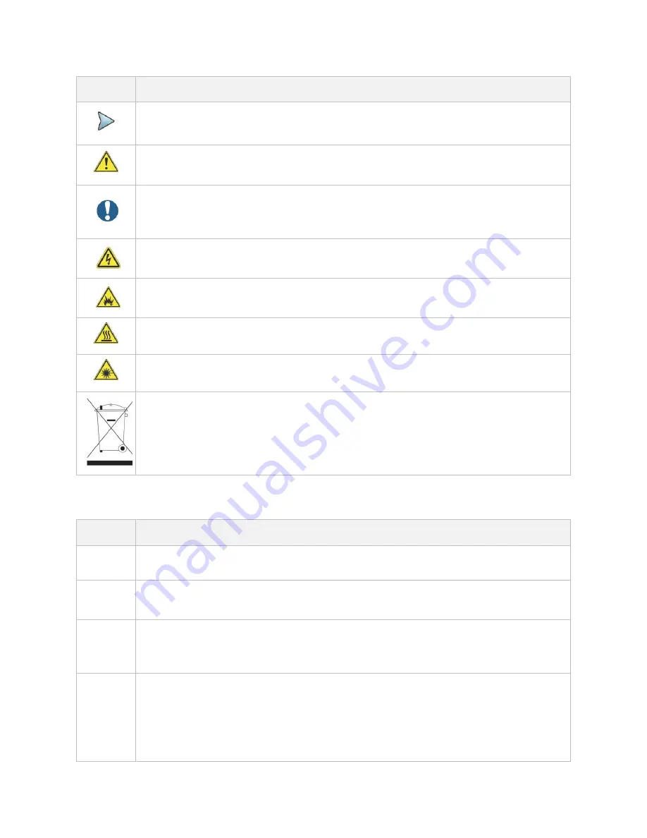
This symbol indicates a note that includes important supplemental information or tips 
related to the main text. 


T

his symbol represents a general hazard. It may be associated with either a DANGER, 

WARNING, CAUTION, or ALERT message. 


This symbol represents an alert. It indicates that there is an action that must be performed 
in order to protect equipment and data or to avoid software damage and service 
interruption. 


This symbol represents hazardous voltages. It may be associated with either a DANGER, 
WARNING, CAUTION, or ALERT message. 


This symbol represents a risk of explosion. It may be associated with either a DANGER, 
WARNING, CAUTION or ALERT message. 


This symbol represents a risk of a hot surface. It may be associated with either a DANGER, 
WARNING, CAUTION, or ALERT message. 


This symbol represents a risk associated with fiber optic lasers. It may be associated with 
either a DANGER, WARNING, CAUTION or ALERT message 


This symbol, located on the equipment, battery, or the packaging indicates that the 
equipment or battery must not be disposed of in a land-fill site or as municipal waste, and 
should be disposed of according to your national regulations. 

Safety definitions 

Term


Definition


NOTE 

Indicates important supplemental information or tips related to the main text. 

DANGER 

Indicates a potentially hazardous situation that, if not avoided, will result in death or serious 
injury. It may be associated with either a general hazard, high voltage, or other symbol. 

WARNING 

Indicates a potentially hazardous situation that, if not avoided, could result in death or 
serious injury. It may be associated with either a general hazard, high voltage, or other 
symbol. 

CAUTION 

Indicates a potentially hazardous situation that, if not avoided, could result in minor or 
moderate injury and/or damage to equipment. It may be associated with either a general 
hazard, high voltage, or risk of explosion symbol. 

When applied to software actions, indicates a situation that, if not avoided, could result in 
loss of data or a disruption of software operation. 

Summary of Contents for CAA06M

Page 1: ...ralia Enabling Australia s Field Technicians to build troubleshoot and maintain better communications networks Industry Best Pricing Finance Available Short to Medium Project Based Rental Solutions Dedicated Technical After Sales Support In house Diagnostics Repair NATA Calibration Laboratory FREECALL 1800 680 680 ...

Page 2: ...1 CAA06M Cable and Antenna Analyzer User s Guide ...

Page 3: ......

Page 4: ...s 9 Features 9 Capabilities 10 Specifications 10 Physical specifications 10 Power supply specifications 10 Environmental specifications 10 Options 11 Getting Started 13 Unpacking and inspecting CAA06M Cable and Antenna Analyzer 13 Installing Dual Module Carrier and CAA06M Cable and Antenna Analyzer 13 Navigating the user interface 15 Glancing at menus and icons 15 Setting up the instrument 17 Enab...

Page 5: ...Introduction 25 Introducing reflection measurement 25 Preparing for a measurement 27 Selecting measurement mode 27 Setting parameters 27 Making a measurement 29 Procedure 29 Analyzing measurement results 30 DTF Testing 35 Introduction 35 Introducing DTF measurements 35 Preparing for a measurement 36 Selecting measurement mode 36 Setting parameters 36 Making a measurement 40 Procedure 40 Analyzing ...

Page 6: ...ducing 1 port phase measurements 51 Preparing for a measurement 52 Selecting measurement mode 52 Setting parameters 52 Making a measurement 54 Procedure 54 Analyzing measurement results 55 Smith Chart Testing 57 Introduction 57 Introducing Smith chart measurements 57 Preparing for a measurement 58 Selecting measurement mode 58 Setting parameters 58 Making a measurement 60 Procedure 60 Analyzing me...

Page 7: ...sults 67 CW Signal Generating 69 Introduction 69 Introducing RF source 69 Using RF source 70 Selecting measurement mode 70 Turing on RF source 70 Analysis 71 Introduction 71 Using zoom zones 71 Setting sub band frequency 71 Tips for zoom zones 71 Using alternate DTF band 72 Setting alternate DTF band 72 Using markers 73 Setting a marker 74 Moving hiding and clearing a marker 75 Searching for peak ...

Page 8: ...g traces 76 Adding a trace 76 Performing trace math 77 Loading a saved trace 77 Setting test limits 78 Setting a limit line 78 Setting a Multi Segment limit Line 79 Setting a limit window 81 Holding a measurement 82 Appendix 83 A Ordering information 83 B RoHS information 85 ...

Page 9: ......

Page 10: ...ions Inc VIAVI All other trademarks and registered trademarks are the property of their respective owners No part of this guide may be reproduced or transmitted electronically or otherwise without written permission of the publisher Google Maps and Google Earth are either trademarks or registered trademarks of Google in the United States and or other countries Android is a trademark or a registere...

Page 11: ...r instrument The authority to operate this product is conditioned by the requirements that no modifications be made to the equipment unless the changes or modifications are expressly approved by VIAVI Caution To comply with FCC RF exposure compliance requirements a separation distance of at least 20 cm must be maintained between the antenna of this device and all person This transmitter must not b...

Page 12: ...isposed of according to your national regulations VIAVI has established a take back processes in compliance with the EU Waste Electrical and Electronic Equipment WEEE Directive 2012 19 EU and the EU Battery Directive 2006 66 EC Instructions for returning waste equipment and batteries to VIAVI can be found in the WEEE section of VIAVI Standards and Policies web page If you have questions concerning...

Page 13: ...Power Control Guide conventions This guide uses the following conventions Typographical conventions Description Example Buttons that the user presses or tap on a physical device Press the ON button Screen buttons menus icons and options that you tab select on the touch screen in this typeface Tap the Apply button Tap Limit line to turn on Go to Settings Select Channel standard A single slanted bra...

Page 14: ...UTION or ALERT message This symbol located on the equipment battery or the packaging indicates that the equipment or battery must not be disposed of in a land fill site or as municipal waste and should be disposed of according to your national regulations Safety definitions Term Definition NOTE Indicates important supplemental information or tips related to the main text DANGER Indicates a potenti...

Page 15: ... protect equipment and data or to avoid software damage and service interruption Technical assistance If you require technical assistance call 1 844 GO VIAVI or send an email to TAC viavisolutions com For the latest TAC information go to http www viavisolutions com en services and support support technical assistance ...

Page 16: ...strument for properly servicing or installing cell sites The CAA06M analyzer is the optimal test solution to characterize cell site s infrastructure due to its ease of use and rich functionality The CAA06M analyzer has all of the measurement functions necessary to accurately verify the site s transmission line and antenna system from signal reflections VSWR or Return Loss to DTF Distance to Fault ...

Page 17: ...Introduction to CAA06M 8 ...

Page 18: ... cellular base stations and cell sites running with external AC power or battery for the field Its touch based user interface has been specifically designed with customized menus and simple calibration procedures providing service providers with accurate and reliable measurement results Features Up to 2001 data points to locate long distance problems Dual display to view multiple measurements simu...

Page 19: ...ironmental characteristics for the CAA06M Cable and Antenna Analyzer installed at CellAdvisor 5G are listed in the tables below Physical specifications Product Dimension H x W x D Weight CAA06M Cable and Antenna Analyzer 130 mm x 138 mm x 41 mm 0 43 kg for CAA06MA 0 45 kg for CAA06MB CellAdvisor 5G with CAA06M Cable and Antenna Analyzer 309 mm x 241 2 mm x 159 4 mm 7 25 kg Power supply specificati...

Page 20: ...8800F Class 2 Altitude up to 4600 m Overvoltage category Overvoltage category OVC1 Pollution degree Pollution degree 2 Operation Temperature 10 to 55 C Storage Temperature 40 to 70 C Options This instrument is provided with various options features that are available to be ordered See Appendix A Ordering information for more information ...

Page 21: ......

Page 22: ...amage contact VIAVI Customer Care at 1 844 GO VIAVI For the latest TAC information go to https www viavisolutions com en us services and support support technical assistance CAA06M must be installed at Dual Module Carrier Figure 1 Dual Module Carrier with CAA06M Installing Dual Module Carrier and CAA06M Cable and Antenna Analyzer You need to install the Dual Module Carrier to CellAdvisor 5G if you...

Page 23: ...lAdvisor 5G and perform the O S L Calibration by tapping the Cal in the right side bar on the screen The instrument displays on screen instructions for you to follow through NOTE The dummy module is intended to protect the rear connectors on the Dual Module Carrier and it is recommended to install a dummy module for any connector not in use For the customer who wants to order the dummy module the ...

Page 24: ...nalyzer efficiently Menus on the side bar Items Name Description Menu Tap to view all menus for the selected measurement and mode Note that the Menus vary based on the selected measurement and mode Full menu Tap to view full menus for the selected measurement and mode in one screen You can set all the parameters needed for a test at once More Tap to view more hot keys available ...

Page 25: ...set the marker position Peak Search Tap to set the active marker to peak When makers are all off M1 will be the active marker Screen Capture Tap to quick save the current screen Calibration Tap to perform calibration The on screen instruction appears to guide you through the calibration Preset Tap to reset the instrument to the factory default It can be shown when you tap the more icon on the side...

Page 26: ...left in the trial is indicated to the right When the trial period ends a warning message appears If you are running a test when the option expires you can continue testing but the expiration warning will reappear every minute until you either enter a permanent option code or reset the module changing applications will reset the module Option has not been enabled If you need this option contact reg...

Page 27: ......

Page 28: ...e the following calibration tools to be able to perform a calibration This instrument detects the connected calibration kit and displays a different on screen instruction for it Mechanical Y Cal kit or electronic EZ Cal kit Note In case of calibration with Ez Cal there is no Cal Off T Extension cable s if necessary Performing 1 port Calibration Measurement modes that need the 1 port calibration ar...

Page 29: ...button The calibration progress bar appears 5 Disconnect the calibration kit and then connect the SHORT standard of the calibration kit to the instrument s the Reflection RF Out port or to the extension cable if used 6 Tap the Continue button The calibration progress bar appears 7 Disconnect the calibration kit and then connect the LOAD 50 Ω standard of the calibration kit to the instrument s the ...

Page 30: ...edure 1 Connect an extension cable if necessary to the Reflection RF Out port of the instrument 2 Connect the EZ Cal to the instrument s Reflection RF Out port or to the extension cable if used 3 Connect the USB cable to the side of the EZ Cal and then to the USB Host port to power the e calibration kit 4 Tap Cal icon in the right side bar The on screen instruction appears to guide you through the...

Page 31: ...e screen to see if the calibration status is now changed to Cal ON 7 After the electronic calibration has been completed the EZ Cal kit changes its status back to Open 7 Make sure to disconnect the EZ Cal kit including its USB connection ...

Page 32: ...port of the instrument 2 Tap Cal icon in the right side bar The on screen instruction appears containing the Quick Cal button 3 Connect the OPEN standard of the calibration kit to the instrument s the Reflection RF Out port or to the extension cable if used 4 Tap the Quick Cal button The calibration progress bar appears 5 Check the screen to see if the calibration status is now changed to Cal ON Q...

Page 33: ... calibration as described in the previous pages Thru calibration Procedure 1 Connect the test cable to the Reflection RF Out port and RF In port of the instrument 2 Tap Thru Cal to start calibration A progress bar is displayed to show the calibration progress in percentage 3 Check the screen to see if the calibration status is now changed to Cal ON ...

Page 34: ...e direction it is produce an interference pattern called a standing wave VSWR is the ratio between the power that is sent forward to the cable and or antenna and the amount of the power that is reflected back to the transmitter Some of the consequences of having a high VSWR condition in cellular services are dropped calls poor reception and an overall unacceptable performance in the cell or sectio...

Page 35: ...imply as 3 dB of loss dropping the negative sign and adding loss For example if a device has 15 dB of return loss the reflected energy from that device PR is always 15 dB lower than the transmitted energy PT When expressed in dB larger in magnitude negative numbers represent larger return losses and thus smaller reflected power PR In electrical systems return losses often occur at junctions betwee...

Page 36: ...Input the values of Start Frequency Stop Frequency Center Frequency Span Frequency using the on screen keyboard and tap Apply 3 To select a band tap the Band List then it displays a list of standard bands stored in the instrument and custom bands created in the JDViewer Tap your choice from the list and tap the Apply button on the Band List box The instrument automatically updates the values of th...

Page 37: ... Menu key on the side bar and tap General 2 To set the measurement resolution select the Data Points option from the choices 126 251 501 1001 and 2001 NOTE Default setting is 1001 It is recommended that you select high resolution data points only for an instance of measuring wide frequency bands or requiring precise measurement data The larger number you choose the higher resolution you get and th...

Page 38: ...on measurement in VSWR or Return Loss Procedure 1 Disconnect the calibration kit from the calibration point 2 Connect an antenna or feed line to the calibration point which is usually at the extension cable end if used 3 Your measurement result is displayed on the screen in real time CAUTION Do not apply or connect power exceeding 30 dBm to the Reflection RF Out port When the input signal power is...

Page 39: ...ue 6 Set the parameters appeared on the table below the chart screen as needed Analyzing measurement results You can use the Marker Peak Trace Limit Hold and Auto Scale hard keys and Zoom Zone function for your analysis of the results You can also use Quick Save Save and Load functions See Analysis and Operation for details Reflection VSWR measurement screen single layout Reflection VSWR measureme...

Page 40: ...CAA06M User s Guide 31 Reflection return loss measurement screen single layout Reflection return loss measurement screen zoom zones ...

Page 41: ...Reflection Test 32 Reflection VSWR DTF return loss measurement screen horizontal layout Reflection return loss smith chart measurement screen vertical layout ...

Page 42: ...CAA06M User s Guide 33 ...

Page 43: ......

Page 44: ...lections or discontinuities from various points of the transmission system In DTF measurements the instrument transmits a test signal along the conductor or transmission medium If the conductor is of uniform impedance and properly terminated the entire transmitted signal will be absorbed in the far end termination and no signal will be reflected toward the instrument Any impedance discontinuities ...

Page 45: ...n choose two measurement modes from each window in the Horizontal or Vertical tab if you want to view dual measurements displayed on one screen Setting parameters Frequency You can manually set a frequency band to be measured by entering start and stop frequencies or center and span frequencies You can also select a frequency band from the band list stored in the instrument It ...

Page 46: ...ances The maximum measurable distance is dependent on the frequency you set You can set any values within the maximum measurable distance but optimum resolution is achieved when you set the distance same as the maximum measurable distance which is displayed in the measurement setting information bar at the bottom of the measurement screen 1 Tap the Menu key on the side bar and tap Distance 2 Input...

Page 47: ... Interference Rejection feature select On NOTE Default setting is Off It is recommended to use this feature only when you suspect interfering signals in the area as it slows down measurement 4 To set the method of video filtering to display the trace select the Windowing option from the following choices Rectangular Blackman Nominal Side Low Side and Minimum Side NOTE If the video filtering is act...

Page 48: ... the list and then tap Apply on the Cable List window The instrument automatically changes the Propagation Velocity and Cable Loss values correspondent to the selected cable s propagation velocity and cable loss Default setting is HFC 12D 1 2 4 If you want to define a new cable select the Propagation Velocity field and then enter the propagation velocity of the cable using the on screen keyboard a...

Page 49: ... usually at the extension cable end if used 3 Your measurement result is displayed on the screen in real time CAUTION Do not apply or connect power exceeding 30 dBm to the Reflection RF Out port When the input signal power is greater than 30 dBm it may cause a damage to the CAA module and instrument NOTE If O S L or Quick calibration has been done at the end of the port extension cable for DTF mea...

Page 50: ...k Trace Limit Hold and Auto Scale hard keys and Zoom Zone function for your analysis of the results You can also use Quick Save Save and Load functions See Analysis and Operation for details DTF VSWR measurement screen single layout DTF return loss measurement screen single layout ...

Page 51: ...DTF Testing 42 DTF return loss measurement screen Alt DTF Band on Reflection VSWR DTF return loss measurement screen horizontal layout ...

Page 52: ...CAA06M User s Guide 43 DTF VSWR Smith chart measurement screen vertical layout ...

Page 53: ......

Page 54: ...easurements The 1 Port Cable Loss measurement checks the signal attenuation level of the cable The frequency band to measure the characteristics of a cable must be calibrated before performing the cable loss measurement This measurement can be especially useful in measuring the loss of feed line connected to the antenna By placing a short at the end of the cable or leaving it open the signal is re...

Page 55: ...ontal or Vertical tab if you want to view dual measurements displayed on one screen Setting parameters Frequency You can manually set a frequency band to be measured by entering start and stop frequencies or center and span frequencies You can also select a frequency band from the band list stored in the instrument It is desirable to set the frequency to a value that covers a normal range of the m...

Page 56: ...nd minimum values of the Y scale manually by setting the Top and Bottom amplitudes or restore the instrument s default full scale defined for each measurement mode You can also optimize the Y scale automatically so that an entire trace can be displayed on the measurement chart Adjusting Y scale does not affect calibration status 1 Tap the Menu key on the side bar and tap Amplitude 2 Input the valu...

Page 57: ...tion feature select On NOTE Default setting is Off It is recommended to use this feature only when you suspect interfering signals in the area as it slows down measurement 4 For users with the Bias Tee installed To use the Bias Tee Select On for the Bias Voltage and input a value between 12 and 30 with 1 V step as you desire Tap Apply to save the changes NOTE If you have set this Bias Voltage to O...

Page 58: ...ay cause a measurement error Analyzing measurement results You can use the Marker Peak Trace Limit Hold and Auto Scale hard keys and Zoom Zone function for your analysis of the results You can also use Quick Save Save and Load functions See Analysis and Operation for details 1 port cable loss measurement screen single layout 1 port cable loss measurement screen zoom zones ...

Page 59: ...1 Port Cable Loss Testing 50 ...

Page 60: ...matching and phase match cables Topics discussed in this chapter are as follows Introducing 1 port phase measurements Preparing for a measurement Making a measurement Introducing 1 port phase measurements You can use 1 Port Phase mode to measure S11 phase when you want to tune antennas and phase match cables 1 port phase measurement screen ...

Page 61: ...reen keyboard and tap Apply 3 To select a band tap the Band List then it displays a list of standard bands stored in the instrument and custom bands created in the JDViewer Tap your choice from the list and tap the Apply button on the Band List box The instrument automatically updates the values of the Start Frequency and Stop Frequency according to the selected band NOTE Frequency changes after c...

Page 62: ...ta Points option from the choices 126 251 501 1001 and 2001 NOTE Default setting is 1001 It is recommended that you select high resolution data points only for an instance of measuring wide frequency bands or requiring precise measurement data The larger number you choose the higher resolution you get and the longer the instrument takes to sweep and display results For example selecting 501 data p...

Page 63: ...he calibration kit from the calibration point 2 Connect an antenna or feed line to the calibration point which is usually at the extension cable end if used 3 Your measurement result is displayed on the screen in real time CAUTION Do not apply or connect power exceeding 30 dBm to the Reflection RF Out port When the input signal power is greater than 30 dBm it may cause a damage to the CAA module a...

Page 64: ...can use the Marker Peak Trace Limit Hold and Auto Scale hard keys and Zoom Zone function for your analysis of the results You can also use Quick Save Save and Load functions See Analysis and Operation for details 1 port phase measurement screen single layout ...

Page 65: ......

Page 66: ...mith chart measurements Preparing for a measurement Making a measurement Introducing Smith chart measurements You can view reflection measurements in Smith Chart which is used to display impedance matching characteristics in the cable and antenna system as well as filter and duplexers devices It helps you graphically identify problems with transmission lines Smith chart measurement screen ...

Page 67: ...b if you want to view dual measurements displayed on one screen Setting parameters Frequency You can manually set a frequency band to be measured by entering start and stop frequencies or center and span frequencies You can also select a frequency band from the band list stored in the instrument It is desirable to set the frequency to a value that covers a normal range of the measurement with enou...

Page 68: ...and Bias Tee 1 Tap the Menu key on the side bar and tap General 2 To set the measurement resolution select the Data Points option from the choices 126 251 501 1001 and 2001 NOTE Default setting is 1001 It is recommended that you select high resolution data points only for an instance of measuring wide frequency bands or requiring precise measurement data The larger number you choose the higher res...

Page 69: ...now ready to make a cable loss measurement Procedure 1 Disconnect the calibration kit from the calibration point 2 Connect an antenna or feed line to the calibration point which is usually at the extension cable end if used 3 Your measurement result is displayed on the screen in real time CAUTION Do not apply or connect power exceeding 30 dBm to the Reflection RF Out port When the input signal pow...

Page 70: ...nd Auto Scale hard keys and Zoom Zone function for your analysis of the results You can also use Quick Save Save and Load functions See Analysis and Operation for details Smith chart measurement screen single layout DTF VSWR Smith chart measurement screen vertical layout ...

Page 71: ...Smith Chart Testing 62 ...

Page 72: ...n line expressed as the ratio of the signal power delivered to that part of the line following the device to the signal power delivered to that same part before insertion Insertion loss The insertion loss is the loss of the transmitted signal power resulting from the insertion of a device in a transmission line It is usually expressed relative to the signal power delivered to that same part before...

Page 73: ...words the ratio PR PT should be as close to one as possible which in decibels means as close to 0 dB as possible 2 port transmission measurement screen Preparing for a measurement Selecting measurement mode 1 Tap Single under the Mode Measure 2 Double tap the 2 Port Transmission icon NOTE You can choose two measurement modes from each window in the Horizontal or Vertical tab if you want to view du...

Page 74: ...within the registered bands the status turns into CAL ON I and it does not require re calibration If changed off the registered band the status turns into CAL OFF and it requires re calibration Amplitude You can set maximum and minimum values of the Y scale manually by setting the Top and Bottom amplitudes or restore the instrument s default full scale defined for each measurement mode You can als...

Page 75: ...n choose the Output Power between 30 dBm and 5 dBm by 1 dB step NOTE Changing the output power level after calibration affects the calibration status and it requires you to perform a new calibration 4 To set the number of measurements to be averaged tap Average and enter a value between 1 and 100 5 To enable the Interference Rejection feature select On NOTE Default setting is Off It is recommended...

Page 76: ...e Reflection RF Out port 3 Your measurement result is displayed on the screen in real time NOTE Do not change the connected port extension cable or frequency settings or it may cause a measurement error Analyzing measurement results You can use the Marker Peak Trace Limit Hold and Auto Scale hard keys and Zoom Zone function for your analysis of the results You can also use Quick Save Save and Load...

Page 77: ...2 Port Transmission Testing 68 ...

Page 78: ...tor function Topics discussed in this chapter are as follows Introducing RF source Using RF source Introducing RF source If RF CW Source option CA5000 S006 is installed on your instrument you can use the RF Source feature to provide different power levels as like using a CW signal generator RF source screen ...

Page 79: ... RF Source feature to generate a CW signal of different output power levels 1 Tap Frequency box and input a value within the frequency range of your instrument between 12 5 MHz and 6 GHz by using the on screen keyboard and tap Apply 2 To set the output level of the CW signal to be injected tap Power Level box and enter a value within the output range for the frequency you have set between 30 dBm a...

Page 80: ...th a single measurement window You can use the Zoom function to have a closer look at the user definable zoom zones in different windows up to four zones All the four zoom zones are turned off by default It is available for Reflection 1 Port Cable Loss 1 Port Phase and 2 Port Transmission measurement in the single layout view Setting sub band frequency 1 Tap the Menu key on the side bar and tap Zo...

Page 81: ...F Band that is available only in DTF measurements after a calibration to scale down of a specific sub band without a need of an additional calibration Two independent sweeps can be performed for example one Reflection measurement and the other DTF measurement Setting alternate DTF band 1 Tap the Menu key on the side bar and tap Alt DFT Band If you have dual displays on the screen make sure to sele...

Page 82: ...rs on the measurement display simultaneously The instrument displays the Marker menu in the side bar on the screen As you set a marker on the trace you can see readouts of each marker position that is displayed in its marker screen key on the Marker screen menu bar A colorful marker indicates that the marker is the active marker now and you can manipulate it as you like including changing marker t...

Page 83: ... normal marker and the marker s X and Y values display the difference compared with the Delta marker The reference position will be fixed This setting is not used in the Smith Chart measurement mode Delta Pair A Delta Pair marker is associated with a Normal marker A Normal marker must be set before a Delta Pair marker is set When the Delta Pair marker is set the position set by the Delta Pair mark...

Page 84: ...wing steps Tap the active marker on the screen and tap the Marker to Off To have the marker back on the screen tap the Marker to On NOTE The instrument keeps the last status of marker type and position internally so that you can have the marker back on the trace with the previous information when you select Marker On in the same measurement mode 3 To clear all the markers displayed on the chart ta...

Page 85: ...ker setting If you tap the Find 4 Peaks Valleys the Always Peak Valley automatically changes to Off Always Peak Valley Searches for the highest peak or valley on the trace automatically every time the trace is refreshed Peak Valley Between 1 Searches for the highest peak or valley in between M1 and M2 and automatically assigns M5 if there are M1 and M2 on the trace Peak Valley Between 2 Searches f...

Page 86: ... choose and tap Trace Clear All Then all the existing traces disappear and the default trace T1 is displayed with measurements Performing trace math If you have the traces T1 and T2 on your measurement chart you can perform trace arithmetic functions 1 Tap Trace and select either Trace 1 or Trace 2 trace Tap Trace Math Type and do one of the trace math functions from the following choices T1 T2 Ad...

Page 87: ...e No from 0 to 9 and Slot No between 0 and 1 based on your need using the on screen keyboard Setting test limits You can define test limits for automatic Pass Fail and Warning indication and display a limit line with single or multiple segments or a limit window It makes it easy to verify that a measurement exceeds defined thresholds with alarming option which sounds if any portion of the trace fa...

Page 88: ...nal To save the limit settings tap Save Setting a Multi Segment limit Line The Multi Segment limit Line MSL is a mask you can define and use to analyze your measurement results 1 Tap Limit in the Menu key on the side bar 2 Select the Alarm Sound option between On and Off If you select On the instrument goes off an alarm when a result falls outside of defined limits 3 Select the Pass Fail result op...

Page 89: ...using the on screen keyboard c To add a new segment tap Segments and input the number of segment you want 9 To move the current MSL line tap Move MSL and enter a value by using the on screen keyboard Optional To save the limit settings tap Save Upper and lower MSL line MSL line with red point ...

Page 90: ... green limit line appears at the set value on the screen 5 To edit the frequency or amplitude value of the limit window segments complete the following steps Tap Move The red point indicates your current selection To select a point to redefine the frequency or amplitude value tap the arrow of Move Each time you tap this key the selection moves to right or left To change the X axis coordinate of th...

Page 91: ...it window Holding a measurement You can put a measurement on hold and resume sweeping as needed 1 Tap Hold icon on the side bar Sweeping is paused 2 To resume the measurement Tap Hold icon again Sweeping is continued ...

Page 92: ...escription CAA06MA 6 GHz Cable and Antenna Analyzer Module CAA06MB 6 GHz Cable and Antenna Analyzer Module with Bias Power and Bias Tee CA5000 DMC Dual Module Carrier with Dummy Module for CellAdvisor 5G CA5000 S005 2 Port Transmission Measurement SW option CA5000 S006 RF CW Source SW option CAA06M CR CAA Module Calibration Report Part s for CAA06M Cable and Antenna Analyzer Accessories Catalog Nu...

Page 93: ... RF cable DC to 6 GHz Type N m to DIN f 1 5 m G700050540 Phase stable RF cable w grip DC to 6 GHz Type N m to Type N f 1 5 m G700050541 Phase stable RF cable w grip DC to 6 GHz Type N m to DIN f 1 5 m G700050571 Adapter Type N m to DIN f DC to 7 5 GHz 50 ohm G700050572 Adapter DIN m to DIN m DC to 7 5 GHz 50 ohm G700050573 Adapter Type N m to SMA f DC to 18 GHz 50 ohm G700050574 Adapter Type N m t...

Page 94: ...0 GHz 50 ohm G700050585 Adapter N m to 4 3 10 f DC to 6 0 GHz 50 ohm G700050586 Adapter N m to 4 3 10 m DC to 6 0 GHz 50 ohm G700050587 Adapter N f to SMA f DC to 18 GHz 50 ohm B RoHS information This appendix describes the RoHS Restriction of Hazardous Substances information which is a mandatory requirement from China The RoHS directive consists in the restriction on the use of certain hazardous ...

Page 95: ...Appendix 86 ...

Page 96: ...ica Toll Free 1 844 GO VIAVI 1 844 468 4284 Latin America 52 55 5543 6644 EMEA 49 7121 862273 APAC 1 512 201 6534 All other regions www viavisolutions contacts Email TAC viavisolutions com Doc No 22134163 Rev 3 00 July 2019 English ...

Reviews: