


2.7 Receiver Tab
The
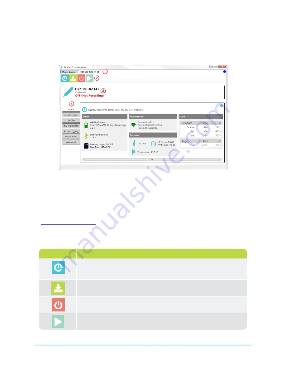
Receiver
tab displays receiver operation buttons and information. Each identified and connected
receiver is shown in its own tab.
Figure 2-3: Receiver Tab
1 -
Receiver Tab Name
is receiver's serial number.
2 -
Operation
buttons.
3 -
Receiver basic information
: Receiver ID/Serial Number, and
ON
(recording) or
OFF
(not
recording) status
4 -
(Status, Live Detections, etc.)
Operation Buttons
Receiver
Operation
buttons include:
Button icon
Button name and description
Set Receiver Clock
button - Sets the receiver's internal clock based on your
computer's current time settings.
Offload Data
button - Initiates data offload to your location of choice on your
computer.
Suspend Receiver
button - Suspends receiver operation. Detections are not
recorded when the receiver is in Suspend Mode.
Start a New Study
button - Clears data on your receiver and starts a new
study.
28
HR2 Receiver User Guide
Summary of Contents for HR2
Page 1: ......
Page 7: ...vi This page intentionally left blank to ensure new chapters start on right odd number pages...
Page 9: ...viii This page intentionally left blank to ensure new chapters start on right odd number pages...
Page 23: ...14 This page intentionally left blank to ensure new chapters start on right odd number pages...
Page 41: ...32 This page intentionally left blank to ensure new chapters start on right odd number pages...
Page 83: ...74 This page intentionally left blank to ensure new chapters start on right odd number pages...
Page 91: ...82 This page intentionally left blank to ensure new chapters start on right odd number pages...
Page 151: ...142 This page intentionally left blank to ensure new chapters start on right odd number pages...
Page 179: ...170 This page intentionally left blank to ensure new chapters start on right odd number pages...
Page 187: ...178 This page intentionally left blank to ensure new chapters start on right odd number pages...
Page 188: ...179 Appendices Appendices...
Page 189: ...180 This page intentionally left blank to ensure new chapters start on right odd number pages...
Page 191: ...182 This page intentionally left blank to ensure new chapters start on right odd number pages...
Page 193: ...184 This page intentionally left blank to ensure new chapters start on right odd number pages...
Page 195: ...186 This page intentionally left blank to ensure new chapters start on right odd number pages...
Page 197: ...188 This page intentionally left blank to ensure new chapters start on right odd number pages...
Page 203: ...194 This page intentionally left blank to ensure new chapters start on right odd number pages...
Page 207: ...198 This page intentionally left blank to ensure new chapters start on right odd number pages...


