Table of Contents
iii
Safety Precautions ............................................................................................................1
Specifications ....................................................................................................................2
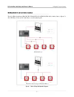
IQ Manifold Control Information ........................................................................................3
Manifolded PLLD – TLS Decides (multiple hook signals).........................................4
Manifolded Direct – Unit 1 always turns on first (One shared hook signal) ..............4
Manifolded Alternating – The devices alternate turning on first every time
the hook signal is disabled. (One shared hook signal) .............................................4
Installation and Wiring Instructions
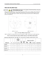
Determine the Motor Type ..............................................................................................10
Programming the Motor Type .........................................................................................13
Setup Switch Chart .........................................................................................................15
Initial Calibration .............................................................................................................16
Uncalibrated Controller...........................................................................................17
Over-Current Condition ..........................................................................................17
Dry Run ..................................................................................................................18
Low AC Current ......................................................................................................18
Setup/Communication Error ...................................................................................18
Low Line Voltage....................................................................................................18
Bypass Mode..........................................................................................................18
Extended Run.........................................................................................................18
Appendix A - TLS-450PLUS Diagnostic Monitoring of
Red Jacket IQ Control Boxes
..........................................................................................
Installing RS-485 Wiring Between IQ Control Boxes & TLS-450PLUS ..........................
Upgrading IQ Control Box Software - Repeat For Each IQ Control Box .........................
TLS-450PLUS RJ IQ Monitoring Feature Installation Procedure ....................................
Verifying RS-485 Single or Dual Comm Module Jumper Positions ................................
Connecting RS-485 Wiring To The IQ Control Boxes ...................................................
TLS-450PLUS Setup For IQ Control Box Monitoring ....................................................
..................................................................................................
.........................................................................................

