6
Installation and Wiring Instructions
This equipment must be installed in a non-hazardous location.
1. Locate an area that allows all of the wiring to enter through the bottom knockouts of the IQ Control Box.
Consider the ability to view the indicator on the side of the base and access to the reset button when
choosing a location.
2. Remove the cover of the enclosure and mount the base.
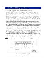
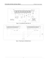
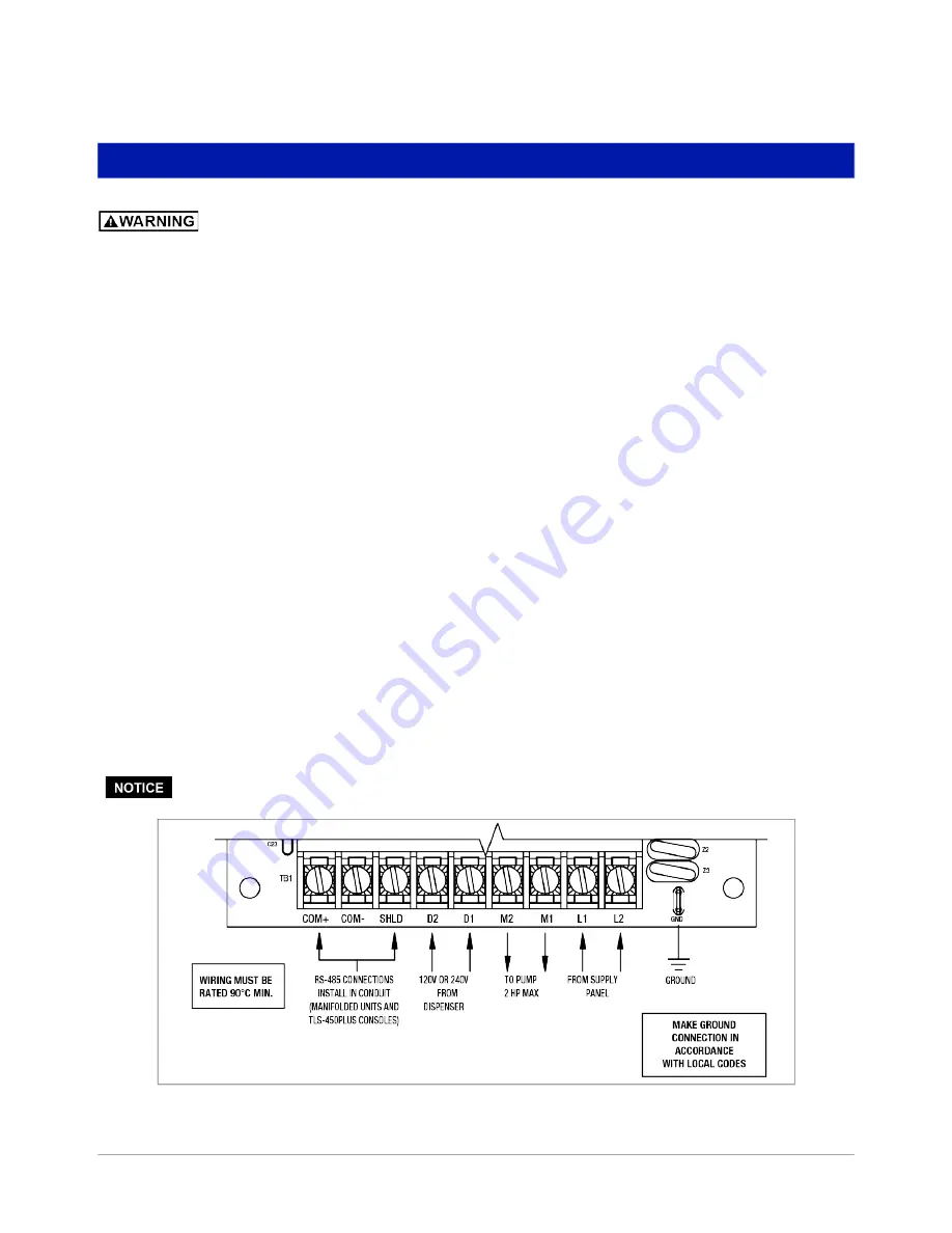
3. While viewing the wiring diagram or inside the enclosure cover, connect the input power L1 and L2 wires to
the terminal block labeled TB1 (see Figure 2). This control box is designed to operate from 200 to 250Vac.
Since the submersible turbine pump is powered by the M1 and M2 terminals (and M3 terminals -058, -059
models) on the circuit board, refer to the installation and instruction manual that was supplied with the pump
for correct supply voltage. Typical pump ratings are 200 to 250 Vac.
4. Locate the grounding lug on the enclosure base and make an electrical ground connection to this point.
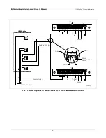
5. Motor leads M1 and M2 should be terminated to the M1 and M2 terminals on TB1. The M3 lead for models -
058 and -059 should terminate to the splice provided lead from the capacitor in the cover (see Figure 3).
6. The D1 and D2 terminals are reserved for the dispenser signal. These terminals are not polarity sensitive and
can accept 120V or 240V signals. For pump manifolded installations it is important to wire the dispenser
signal to all of the controllers.
7. Jumper J3 should be in the Normal position. Use the Bypass position only to program the Motor Type, or if
temporarily controlling the pump directly from dispenser. Pump protection operation is not available in this
position.
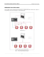
8. Installations that will operate pumps in a manifolded or TLS450PLUS monitoring configuration require a two
conductor, twisted pair with shield (min. 22 AWG) connected to the COM+, COM-, and SHIELD terminals of
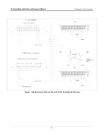
TB1. Daisy chain the communication cable to all of the controllers and/or the TLS-450PLUS as shown in
Figure 4. Belden 3106A, or equivalent cable is acceptable. If adding a TLS-450PLUS monitoring
configuration to an existing controller installation, reuse the existing cable between the controllers. The RS-
485 link between pump controllers is not intended to be connected to other Red Jacket electronic equipment
such as Prolink, CPT, VSFC or other ATG devices. However, it may be necessary to break communications in
PLLD or DPLLD applications as shown in Figure 5 and Figure 6. This cable must be installed in conduit.
Approved component only. Total systems installed shall comply with all codes.
Figure 2. Terminal Block TB1, Models -051, -052

