


A-
1
Appendix A
TLS-450PLUS Diagnostic Monitoring of Red Jacket IQ Control Boxes
Equipment Requirements, Installation and Setup
Introduction
This Appendix provides application, technical and installation guidelines for Veeder-Root certified technicians who
will be installing and setting up the Red Jacket IQ Control Standard Diagnostic Feature with a TLS-450PLUS
system.
Pre-Installation Consideration
Verify site layout and feasibility to install RS-485 communications cables from IQ Control Boxes to TLS-450PLUS
Communications bay.
Equipment Requirements
• TLS-450PLUS System Software Upgrade (9W or Higher)- P/N 330020-744. Software upgrades can be
downloaded from the Veeder Root Web Site Support page https://www.veeder.com/us/software-downloads.
• TLS-450PLUS I button Intelligent Pump Control Feature P/N 332972-028
• P/N 332869-001; Dual Port RS-485 Communications Module
• Red Jacket IQ Control for each STP installed.
• Red Jacket IQ Control Software Prom Version 3.5 or Higher, P/N 349805-001.
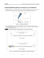
• RS-485 Cabling, shielded cable (Belden 3106A or equivalent SF/UTP cable) - Length as needed between
each RJ IQ Control Box and/or the TLS-450PLUS console - customer supplied.
• RJ-45 Connectors as needed to connect comm cables to TLS-450PLUS RS-485 ports - customer supplied.
• Verify site profile to ensure proper equipment is ordered for the application.
Installation Precautions
It is recommended that the site is shut down during these procedures to ensure no
interruptions during the IQ Control Box programming and calibration procedures.
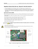
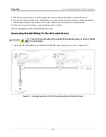
Prior to performing System Software update, I-button upgrade, installation of Dual RS-485 communications
Module in the TLS-450PLUS and the Firmware upgrades in the IQ Control Box(s), it is recommended that the RS-
485 cabling between the TLS-450PLUS and the IQ Control Boxes has been installed to minimize shutdown time
during the system update. (Do not terminate at this time).
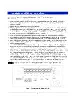
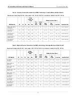
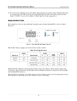
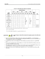
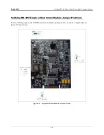
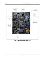
Determining Number of RS-485 Ports Needed
Table A-1 contains the allowable TLS-450PLUS Comm Modules and their permissible slots in the console’s comm
bay.
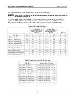
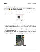
If both RS-232 ports of the dual RS-232 port module (shipped with the console) are being
used you will be limited in the number of RS-485 ports available (Max 3, 2 in Slot 2 and 1
in Slot 3). If only one RS-232 port is being used, you can switch the Dual RS-232 module
for a single RS-232 module, move it to slot 3, leaving slots 1 and 2 open for two dual RS-
485 port modules.


