


IQ Control Box Installation and Owner’s Manual
Description of Fault Conditions
18
WARNING! Before starting this troubleshooting procedure disconnect all
electrical power to the controller including the dispenser inputs. Failure to
do so may
COULD CAUSE DAMAGE TO PROPERTY, ENVIRONMENT, RESULTING
IN SERIOUS INJURY OR DEATH.
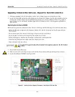
Using an ohmmeter measure the resistance between the M1 and M2 terminals to ground. Ground can be found at
the screw on the enclosure base. Both measurements should be greater than 1Meg ohm. Any measurement less
may indicate a short in wiring between the control box and the submersible pump. The location of the short can be
determined by breaking the wiring connections in the junction box at the pump’s packer/manifold and taking
ohmmeter readings on both sides of the circuit.
Refer to the manual for the extractable pump on instructions for its wiring, servicing, or replacement. Reset the
controller by pressing the reset button momentarily and verify operation once condition is resolved, all wiring
reconnected, and after power is reapplied.
Dry Run
This fault will shut off the pump since the level of the product has fallen below the suction end of the pump. The
controller will automatically reset and start the pump when the next dispenser signal is received. Add fuel to the
tank to restore operation.
Low AC Current
This fault indicates that the submersible pump will not operate. One of the following conditions are present: wire
disconnected resulting in open circuit, thermal switch in motor has opened due to overheating, or the control relay
has failed and the contacts will not close.
Setup/Communication Error
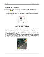
Five red flashes indicate that the controller has detected an improper dip switch setup or a missing connection on
the RS-485 communication cable when set to manifolded operation. Verify that each controller has a unique unit
number setting on the SW1 dip switch. Insure that all controllers have a communication cable connection unless
in standalone mode.
Low Line Voltage
This fault will not shut off the pump but will indicate if at any time the line falls below 200V which is the minimum
specified operating voltage.
Bypass Mode
If jumper J3 is set to bypass this mode will be displayed. Use this only to verify operation between dispenser and
pump since controller cannot provide pump protection in this mode. Return the jumper to the normal condition to
reset this alarm and have the controller monitor the pump.
Extended Run
Use this indicator to signal any pump that has run for more than 6 hours continuously. This may also indicate a
nozzle that has not been properly stowed after dispensing.
Contact Red Jacket Technical Support for additional troubleshooting information at 1-800-323-1799.


