


Appendix A
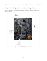
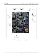
Determining Number of RS-485 Ports Needed
A-2
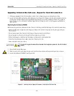
Turn off, tag and lockout the breaker that supplies power to the IQ Control
Box.
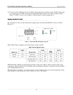
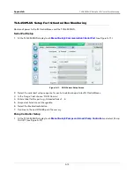
1. Go to each IQ Control Box and determine/record its mode/role setting (DIP SW 1 – See “Setup Switch
Chart” on page
15.) or refer to site documentation to identify IQ Control Boxes that are set to standalone and/
or manifolded mode and their assigned STP/tank.
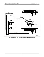
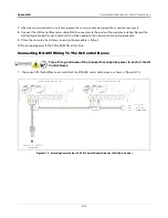
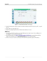
2. If in Standalone mode, up to four independent IQ Control Boxes may be daisy chained to a single RS-485
port.
3. If in one of the manifolded modes, IQ Control Boxes must only be connected to IQ Control Boxes on the same
manifold (one RS-485 port per manifold).
4. Manifolded and direct mode IQ Control Boxes may be combined on the same TLS-450PLUS and may share a
single RS-485 Comm Module as long as they are connected to different RS-485 ports.
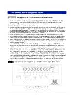
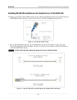
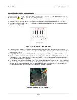
5. After determining the number of RS-485 ports needed for the site, it is recommended to install the site RS-
485 cables.
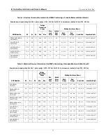
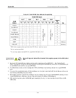
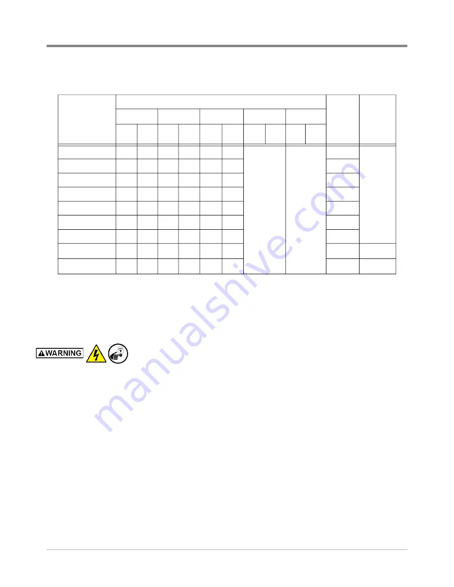
Table A-1. TLS-450PLUS Comm Module Compatibility
COMM
Modules
TLS-450PLUS Console
Modules
Per
System
Type
Slot 1
3
Slot 2
Slot 3
Slot 4
Slot 5
Port
1
Port
2
Port
1
Port
2
Port
1
Port
2
Port
1
Port
2
Por
t1
Port
2
RS-232
l
l
l
E
th
ern
et M
od
ule
(3
P
orts
)
(F
ix
ed
)
U
S
B
M
od
ule
(2
P
orts
)
(F
ix
ed
)
3
Hardware
Dual RS-232
l
l
l
l
3
RS-485
l
l
l
3
Dual RS-485
l
l
l
l
3
RS-232/RS-485
l
l
l
l
3
Internal Modem
l
l
l
3
CDIM
l
l
2
EDIM
1
l
l
l
l
l
3
Software
IFSF LON
2
l
l
l
1
Hardware
1
EDIM can be programmed in any position with an RS-232 port - up to 3 per system
2
Can be combined with EDIM
3
Console ships standard with dual RS-232 or dual RS-232/RS-485 in Slot 1


