17
Troubleshooting
WARNING! If at any time during a troubleshooting procedure the enclosure
must be opened, disconnect controller power prior to removal of the cover.
The input terminals D1 and D2 are powered from the dispenser which is on
a different circuit and may be energized even with the control box power
disconnected. Remember to remove power to dispenser circuits that ener
-
gize the D1 and D2 terminals of TB1 whenever removing power to service
the unit.
Basic Indicator Functions
• Solid green – controller circuit is energized
• Flashing green – pump is running
Description of Fault Conditions
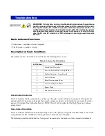
The indicator on the side of the enclosure flashes the following alarms in red:
Uncalibrated Controller
This fault indicates that the controller has not been run through an initial calibration to setup all critical points for
pump protection. The device will operate the pump if a dispenser signal is detected but cannot correctly monitor
pump until initialized. See Calibration Section. NOTE: The unit will not calibrate if the Motor Type has not been
programmed.
Over-Current Condition
This fault indicates that the device detected a high current in the pump’s wiring which could be either a short in the
wiring between the M1 and M2 terminals to ground or a locked rotor in the pump.
The following procedure will determine if wiring must be replaced or the pump must be removed and replaced.
Table 8. Indicator Fault Conditions
# of Flashes
Condition
1
Uncalibrated Controller
2
Over-current Condition – Pump Shutoff
3
Dry Run Detected – Pump Shutoff
4
Low AC Current
5
Setup/Communication Error
6
Low Line Voltage < 200Vac
7
Bypass Mode
8
Extended Run Condition

