IQ Control Box Installation and Owner’s Manual
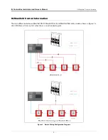
IQ Manifold Control Information
4
Manifolded PLLD – TLS Decides (multiple hook signals)
Overview
In this mode the devices operate while being networked together over RS485 and with a PLLD installation. In this
scenario, each IQ box receives a separate hook signal from the TLS. The TLS is then able to turn on the devices
with a hook signal to activate a PLLD test. Essentially any device can be turned on first via hook switch. The
helping units will then initialize the turn on sequentially over their own RS485 communication.
Operating Example
When a pump request is made by a dispenser the TLS receives the signal. The TLS then decides which pump to
turn on first. This can be based on which tank has the highest fuel height. After the TLS sends the hook signal to
the designated device it begins pumping. As more nozzles are opened there becomes a point where the power
drawn by the motor reaches its threshold. At this point the IQ box sends a request for the next device in line to turn
on in conjunction with itself. For example, the TLS turns on IQ Box Unit 2 first because that was in the tank with
the most volume. When the power threshold is reached Unit 2 will send a request over RS485 for the next unit in
line to turn on. Unit 3 will then turn on and acknowledge the request was complete. If more nozzles are opened yet,
unit 3 will send a request for the next unit in line to turn on over RS485. All pumps once turned on continue to stay
on until the active hook signal is disabled. Once disabled they will all turn off. This process repeats at the next
active hook signal.
Manifolded Direct – Unit 1 always turns on first (One shared hook signal)
Overview
In this setup the Unit 1 always turns on first with a hook signal. The helping units will then turn on sequentially. All
units share a hook signal in this mode, so all units have the hook signal engaged and the hook is controlled by the
Master Hook switch.
Operating Example
When a pump request is made by a dispenser every IQ Box receives this information. Unit 1 will always accept or
try to accept pending any faults. Once it acknowledges it sends out an acknowledged signal over RS485 and all
other IQ boxes will wait in standby for an RS485 message to request to turn on. As more nozzles are opened there
becomes a point where the power drawn by the motor reaches its threshold. At this point the IQ box sends a
request for the next device in line to turn on in conjunction with itself. So, in this case Unit 2 will always turn on
next. Then when Unit 2 is running and more flow is needed it, Unit 3 will be the next to turn on. Lastly Unit 4 will
turn on. All pumps once turned on continue to stay on until the active hook signal is disabled. Once disabled they
will all turn off. This process repeats at the next active hook signal.
Manifolded Alternating – The devices alternate turning on first every time the hook signal is
disabled. (One shared hook signal)
Overview
In this setup the devices take turn passing a token that designates which one will turn on first from a hook signal.
The helping units will then turn on sequentially. All units share one common hook signal in this mode, so all units
have the hook signal engaged and the hook is controlled by the Master Hook switch.
Operating Example
When a pump request is made by a dispenser every IQ Box receives this information. Unit 1 will accept, or try to
accept pending any faults, this initial hook signal and then pass a token for Unit 2 to turn on first at the next pump
cycle. Once Unit 1 acknowledges the hook signal, it sends out an acknowledgment over RS485 and all other IQ
boxes will wait in standby for an RS485 message to request to turn on. As more nozzles are opened there

