


IQ Control Box Installation and Owner’s Manual
Initial Calibration
16
Initial Calibration
Once all of the wiring is complete and the dip switch and jumpers are set the cover can be attached to the
enclosure. Every controller in the system must be calibrated at this time.
WARNING! Power to the controller should only be applied when all wiring is con
-
nected and the cover is installed.
1. Energize the supply voltage to the control box. At this time the indicator on the side of the enclosure should
illuminate green acknowledging circuits are energized. A single red flash from the indicator signals that the
controller has not been calibrated.
2. Press and hold the Reset/Cal button on the side of the enclosure for 10 seconds until the indicator turns red.
3. Release the Reset/Cal button. The controller will automatically start the pump and perform a calibration
procedure. Once the procedure is complete the pump will shut off and the indicator will display solid green.
Should a dispenser handle be lifted during the calibration procedure the controller will suspend the calibration
and dispense fuel as long as the handle remains lifted. A suspended calibration procedure is indicated by
alternating red and green indication through the duration of the dispense event. Once the dispensing event is
over the controller will perform the calibration procedure. Anytime that the pump or dispensing equipment has
been replaced perform a new calibration to update the stored information in memory.
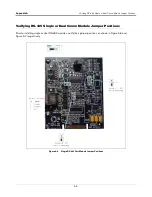
4. The saved Motor Type can be verified with the Bypass jumper in the Normal position.
5. Depress the Reset/Calibration button for 20-seconds – continue holding the button in until the Green LED
has flashed the Motor Type code.
6. If the number of green flashes matches your Motor Type code noted in Step 6. on page 13 above, The IQ
Control Box is now ready for operation.


