Appendix A
Installing RS-485 Comm Module
A-11
Installing RS-485 Comm Module
Disconnect, tag and lockout power to the TLS-450PLUS console be
-
fore starting this procedure.
1. Remove both left and right door screws (with a T-15 Torx driver) and swing open both doors to the left.
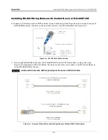
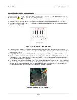
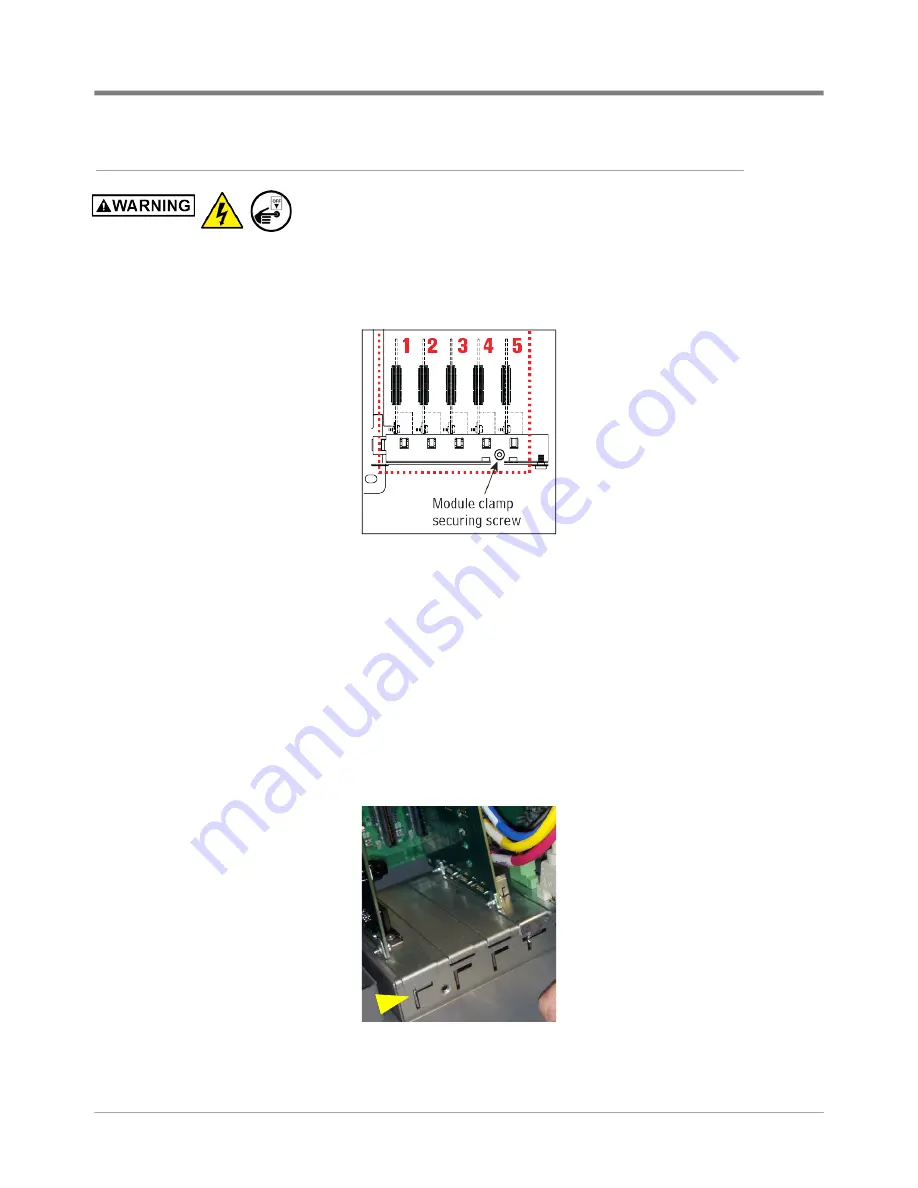
2. On the communications bay, use a T-15 Torx driver to loosen the module clamp securing screw and remove
the clamp (see Figure A-8).
Figure A-8. Comm Module Clamp Securing Screw
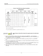
3. The Comm Bay is divided into 5 communication slots numbered from 1 to 5 going left to right. Only slots 1-3
are available for user-selectable Comm modules (ref. Table A-1). The Comm modules in Slots 4 and 5 are fixed
and cannot be moved.
4. Using a T-15 Torx driver, remove the module clamp securing screw (and clamp and set them aside.
5. Remove the blank cover from underneath the desired empty comm slot(s) by punching it into the console or by
using pliers to remove it from the inside of the console. Be careful not to damage any internal components in
the process of removing the blank cover.
6. Place the new RS-485 Comm module(s) in the slot(s). Align the edge connector on the back of the board with
the center of the vertical connector on the Comm Backplane board, then push the module board firmly in as far
as it can go. The sheet metal bracket of the module slides into the comm bay slot and the front edge of the
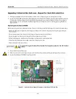
bracket goes into the keyed slot in the front of the Comm Bay (see Figure A-9).
Figure A-9. Comm Module Bracket Keyed Slot

