13
SYMBOLS
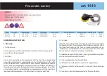
Carefully observe the symbols in fig. B and memorise their
respective meanings. Correct interpretation of the symbols
allows a safer use of the machine.
1 Model, technical data and production batch number.
2 Warning!
3 Carefully read the instructions before use.
4 Wear protective gloves.
5 Wear safety glasses to protect the eyes, as well as ear
protection.
6 Wear a mask to protect your respiratory tracts.
7 Double electric insulation.
8 Electric and electronic waste may contain potentially hazar-
dous substances for the environment and human health. It
should therefore not be disposed of with domestic waste,
but by means of separate collection at specific centres or
returned to the vendor in the event of purchasing a new
identical appliance. Illegal disposal of waste will result in
administrative sanctions.
V Volt
Hz Hertz
~
alternating current
W Watt
mm millimetres
m metres
s seconds
kg kilograms
no speed when idle
min-1
rotations per minute
dB decibel
Thank you for choosing this power tool, hereafter called
‘polisher-sander’.
IMPORTANT! The polisher-sander is suited to the operations
of polishing, sanding and wire brushing of various materials
such as metal, wood and plastic.
It is prohibited to use dangerous materials in environments
with risk of fire/explosion. DO NOT USE FOR GRINDING OR
CUTTING DISCS.
These instructions contain information deemed necessary for
proper use, knowledge and standard tool maintenance. It does
not report information on techniques for the various materials.
The user will find more information in books and specialised
publications or by attending courses.
TECHNICAL DATA
Power 1150 W
Power supply voltage 230V ~ 50Hz
Idle rotation speed 3000 min
-1
Insulation class II
Acoustic pressure level LpA 88,3 dB(A) K=3
Acoustic pressure level LwA 99,3 dB(A) K=3
Vibration level 9.084 m/s2 K=1.5
Backing pad Ø180mm
Threaded shaft connection M14
COMPONENTS
Refer to fig. A
1. Power supply plug and cable
2. Main handgrip
3. Front hand grip
4. Start/stop switch
5. Safety immobiliser device
6. Disc holder shaft lock button
7. Gear box
8. Disc holder shaft
9. Rests and perforations for grip
10. Ventilation slots
11. Voltage indicator
12. Speed regulator
13. Backing pad for polishing/sanding
14. Fabric disc for polishing
15. Key for use
INSTALLATION
IMPORTANT! The manufacturer is not liable for any direct
and/or indirect damage caused by incorrect connections.
IMPORTANT! Before you perform the following steps, make
sure that the plug is disconnected from the AC power supply.
TRANSPORT
Always use the packaging or case (when provided) when
transporting the tool; this will protect it from impact, dust and
humidity which can compromise normal operation.
During transport, remove the abrasive disc, brush, etc. from
the machine.
HANDLING
Firmly grasp the handgrip (fig. 2) without using the switch;
keep the tool well away from your body and after use place it
down gently without hitting the disc.
STARTING UP
When choosing where to use the power tool, the following
should be considered:
- that the area is not damp and is sheltered from the elements.
- that the working area is sufficiently large and free from
obstacles.
- that the area is well lit.
- that the tool is used close to the interrupter switch.
- that the power supply is equipped with an earthing function
in accordance with general rules (only if the tool is in Class
I, and equipped with an earthing cable).
- that the room temperature is between 10° and 35°C.
- that the environment is not in a flammable/explosive atmo-
sphere.
Take out the machine and components and visually check that
they are perfectly intact; then proceed to thoroughly clean them
in order to remove any protective oils from metal surfaces.
FRONT HANDGRIP ASSEMBLY (pos.3)
The handgrip is to be mounted where there are threaded
holes (pos.9).
Position the handgrip and tighten it with the screws provided.
FITTING THE BACKING PAD FOR POLISHING (pos.13)
1) Turn the angle grinder upside down.
2) Temporarily block the rotation of the motor shaft by pressing
the button (pos.6).
3) Tighten by hand and at the base of the pad (pos.13); during
fixing hold the shaft lock button (pos.6).
4) Apply the disc of paper for sanding (if present) or the fabric
polishing disc (pos.14) on the velcro of the pad and at the
centre.
Summary of Contents for L1201
Page 16: ...16...


