background image

Models No.

 Description

PRODUCT

T

ECHNICAL INFORMATION

C

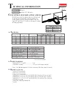
ONCEPTION AND MAIN APPLICATIONS


P 1 / 9 

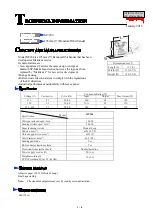
MAKITA new power-file sander enables you to file and sand
in awkward and confined areas, replacing manual work.
Various sanding arms and sanding belt widths, 6mm (1/4'), 
9mm (3/8") and 13mm (1/2'), assure a wider range of sanding
and filing applications.

9032

9mm (3/8") Belt sander

H

W

L

Dimensions : mm  ( " )

Width ( W )

Height ( H )

Length ( L )

420 (16-1/2)

78 (3-1/16)

158 (6-1/4)

Continuous Rating (W)

Voltage (V)

Belt size : mm ( " )

Variable speed switch

Protection from electric shock

Max. sanding length : mm ( " )

Net weight : Kg (lbs)

Power supply cord : m (ft) 

Belt speed : m / min. ( ft / min.)

Cycle (Hz)

Input

Output

Max. Output(W)

110
120
220
230
240

50 / 60
50 / 60
50 / 60
50 / 60
50 / 60

4.8
4.4
2.4
2.3
2.2

Current (A)

S

pecification

S

tandard equipment

O

ptional accessories

< Note >  The standard equipment for the tool shown may differ from country to country.

500

200

500

500

200

500

500

200

500

500

200

500

500

200

500

9 x 533 (3/8 x 21)

300 - 1,700  (980 - 5,600 )

110  (4-5/16) 

Yes

by double insulation

1.5  (3.3)

2.5  (8.2)

* 2.0  (6.6)

* 2.0  (6.6) for Australia

* Sanding belt 9 - 533 grit 80 ......................  2 pcs.
* Dust nozzle assembly ...............................  1 pc. (only for European countries)

* 6mm (1/4") Arm assembly 
* 9mm (3/8") Arm assembly
* 13mm (1/2") Arm assembly
* Sanding belt 6 (1/4") x 533 (21") grit 40,60,80,100,120,(each grit 10 pcs. per pack )    
* Sanding belt 9 (3/8") x 533 (21") grit 40,60,80,100,120, (each grit 10 pcs. per pack) 
* Sanding belt 13 (1/2") x 533 (21") grit 40,60,80,100,120, (each grit 10 pcs. per pack)  

* Dust nozzle assembly 
* Hose 28 for connecting Model 420S
* Joint 25

Summary of Contents for 9032

Page 1: ...put W 110 120 220 230 240 50 60 50 60 50 60 50 60 50 60 4 8 4 4 2 4 2 3 2 2 Current A Specification Standard equipment Optional accessories Note The standard equipment for the tool shown may differ fr...

Page 2: ...2 9031 710 500 350 500 550 533 21 520 20 1 2 455 17 7 8 533 21 533 21 Width mm Length mm Max sanding length mm Max sanding length 110mm 4 5 16 Adjustment of arm angle Tension roller s diameter of stan...

Page 3: ...ith No 1R033 bearing setting plate And set No 1R278 round bar for arbor on pin 4 See Fig 2 Press No 1R278 round bar for arbor with arbor press So ball bearing and 2 pcs of flat washers can be disassem...

Page 4: ...g 4 B Arm holder Arm Arm cover Arm Arm cover Compression spring 6 Arm tensioner Arm holder Set cam lever on on lock position 1 Set cam lever to lock position by pushing it in the direction of arrow as...

Page 5: ...section can be separated from motor unit See Fig 6 2 Take off bracket together with armature by unscrewing tapping screws 4 x 25 as illustrated in Fig 6 A 3 Separate driving roller from armature shaf...

Page 6: ...DW Fig 6 C 7 Assembling driving roller and armature 1 Assemble ball bearing 608DDW to the armature shaft of fan side and assemble insulation washer and ball bearing 627DDW to the armature shaft of com...

Page 7: ...een assembled to motor housing as illustrated in Fig 7 C Bracket Armature Tapping screws 4 x 25 Motor housing Fig 7 C Tapping screws M4 x 18 1 Take off tapping screws 4 x 18 and inserting screwdriver...

Page 8: ...4 Controller 1 2 Switch Field Color index of lead wires Black White Orange Noise suppressor Power supply cord 1 2 3 4 Controller 1 2 Switch Field Noise suppressor Power supply cord Choke coil Field In...

Page 9: ...Wiring diagram P 9 9 Controller Pass the lead wires of power supply cords and the same ones of controller through the space of another side of control dial as illustrated below...

Reviews: