background image

PRODUCT

P 1/ 1

2

Model No.
Description

C

ONCEPT AND MAIN APPLICATIONS

SA4540C/ SA4542C, SA5040C/ SA5042C
Angle Sanders 115mm (4-1/2"), 125mm (5")

For Models SA5040C/ SA5042C

Rubber pad 115

Lock nut 14-48

Abrasive disc 125-24, 30, 50, 80, 120

Abrasive disc (Hook and loop type) 125-40, 60, 80, 120, 180

Wire cup brush 90 set

Wheel cover for wire cup brush 90

Dust collecting wheel cover

etc.

For Models SA4540C/ SA4542C

Rubber pad 100

Lock nut 14-48

Abrasive disc 115-24, 30, 50, 80, 120

Abrasive disc (Hook and loop type) 115-40, 60, 80, 120, 180

Wire cup brush 90 set

Wheel cover for wire cup brush 90

Dust collecting wheel cover

etc.

L

H

W

1,400W Angle sander series models, SA4540C, SA4542C, SA5040C and 

SA5042C are successor models of 9565CVL, featuring:
• 

"

Super Joint System II

"

 developed for effective vibration absorption

• Electronic current limiter, speed control and soft start

• Anti-restart function (f

or

 models SA4540C, SA5040C only

)

• Re-designed durable gear housing

• Ergonomically best possible barrel grip

S

pecification

Continuous Rating (W)

Voltage (V)

Cycle (Hz)

Input

Output

840

Max. Output (W)

110

120

220

230

240

13

12

6.7

6.4

6.1

50/60

50/60

50/60

50/60

50/60

1,400

1,400
1,400

1,400

1,400

2,100

2,100

1,800

2,000

2,100

Current (A)

840

127

12

50/60

---

2,000

840
840

840

840

*1

 with Side grip

Model No.

No load speed: min.

ˉ

¹=rpm

Abrasive disc
Pad

Capacity: mm (")

Protection against electric shock
Power supply cord: m (ft)
Weight according to EPTA-Procedure 01/2003

*

1

: kg (")

European countries except UK: 4.0 (13.2),

Brazil, Australia: 2.0 (6.6), Other countries: 2.5 (8.2)

2,000 - 7,800

Double insulation

115 (4-1/2)

Shock absorbing System

Mechanical brake

Super Joint System II

Yes
Yes
Yes

SA4540C, SA5040C: Yes/ SA4542C, SA5042C: No

Constant speed control

Variable speed control by dial

Soft start
Electronic current limiter
Anti-restart function

Electronic

control

Yes

No

SA5040C/ SA5042C

SA4540C/ SA4542C

125 (5)

105 (4-1/8)

115 (4-1/2)

2.4 (5.2)

S

tandard equipment

Note:

 The standard equipment for the tool shown above may vary by country.

Side grip ................................ 1 (normal type or anti-vibration type) 

Lock nut wrench .................... 1

Pad 115 .................................. 1 (for SA4540C/ SA4542C)

Pad 125 .................................. 1 (for SA5040C/ SA5042C)

O

ptional accessories

T

ECHNICAL INFORMATION
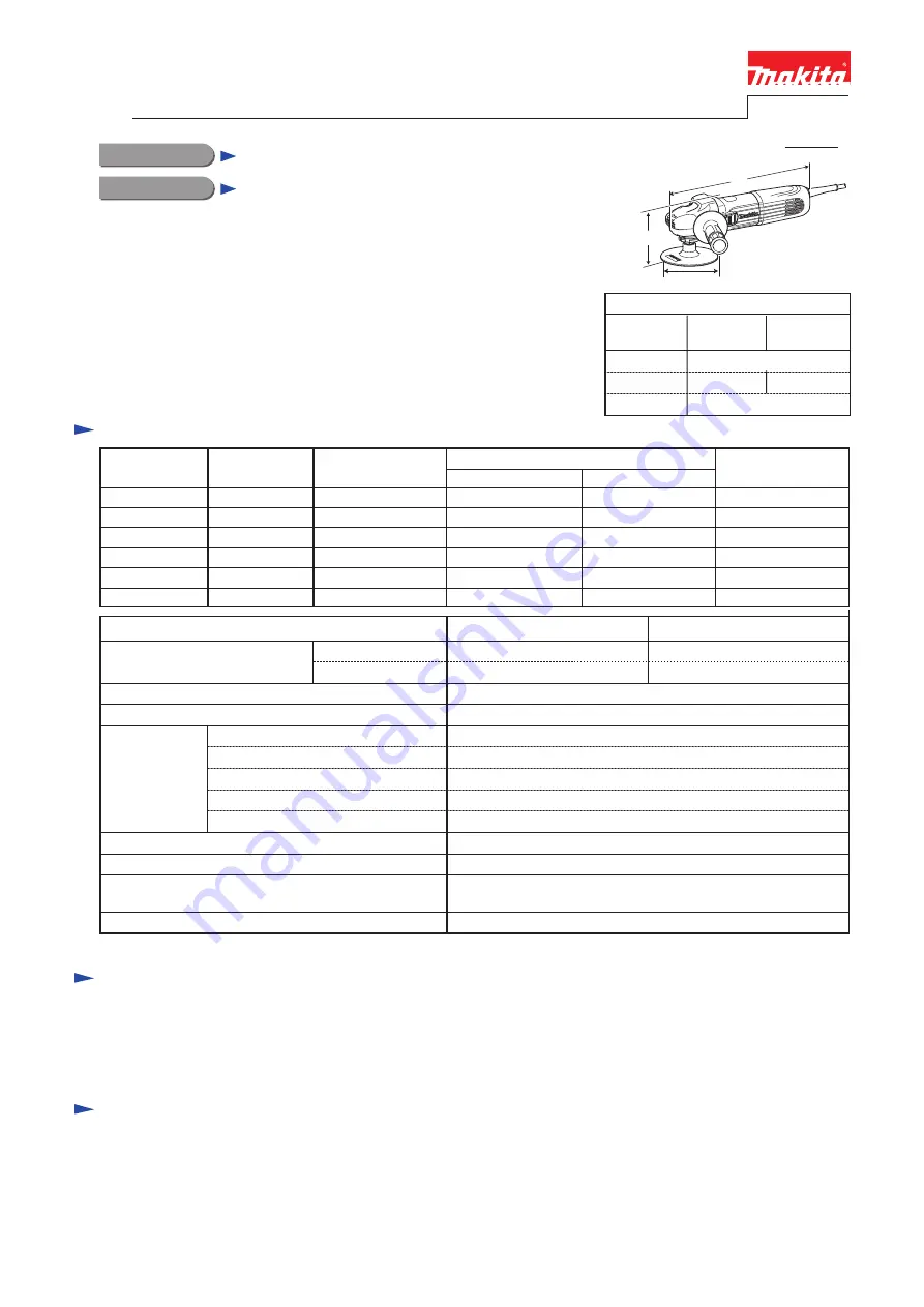
Dimensions: mm (")

Width (W)
Height (H)

Length (L)

105 (4-1/8)

315 (12-3/8)

Model No. SA4540C

SA4542C

121 (4-3/4)

SA5040C

SA5042C

115 (4-1/2)

Summary of Contents for SA4540C

Page 1: ...Input Output 840 Max Output W 110 120 220 230 240 13 12 6 7 6 4 6 1 50 60 50 60 50 60 50 60 50 60 1 400 1 400 1 400 1 400 1 400 2 100 2 100 1 800 2 000 2 100 Current A 840 127 12 50 60 2 000 840 840...

Page 2: ...12 50 removing Spiral bevel gear 37 section from Bearing box 1R291 Retaining ring S R pliers removing Retaining ring S 9 1R340 Bearing retainer wrench removing Bearing retainer 20 33 from Bearing box...

Page 3: ...ver to the groove on Gear housing cover Rear cover 2 Shift Spiral spring from Carbon brush top 3 Disconnect Carbon brush from commutator by pulling up Note No need to remove in this step Groove on Gea...

Page 4: ...bber ring 22 Ball bearing 627DDW 1R269 Flat washer 7 Insulation washer 1 Assemble Spiral bevel gear 7 to Armature end by reversing the disassembly procedure Refer to Fig 2 2 Assemble the commutator en...

Page 5: ...LY 3 2 Armature Spiral bevel gear 7 cont 3 3 Spiral bevel gear 37 Ball bearings 696ZZ 6201DDW DISASSEMBLING Note The gear and the ball bearings can be replaced without disassembling the motor section...

Page 6: ...t washer 12 to the possible eccentric position Then put Bearing box on 1R258 1R049 Spindle 1R050 Spindle Joint sleeve Bearing retainer Bearing box Flat washer 12 4 While applying 1R286 to Flat washer...

Page 7: ...Bearing retainer 20 33 Felt ring 17 Felt ring 17 Flat washer 21 Assemble by reversing the disassembly procedure Refer to Figs 8 7 and 6 Note Do not re use the removed Joint sleeve New Joint sleeve has...

Page 8: ...ly push Switch lever in a direction designated with black arrow 2 Switch lever is disconnected from the locking claw of Switch knob Then remove Switch knob Switch Lever Tumbler Switch Lever 1R284 Swit...

Page 9: ...3 Switch block Controller ASSEMBLING Connect Switch block as drawn in Fig D 3 DISASSEMBLING 3 7 Brush Holder DISASSEMBLING Insert Slotted screwdriver into the gap between Switch and Switch block While...

Page 10: ...st Pin Cap Pin Cap Compression spring 8 1R268 1R350 Fig 14 Fig 15 1 Disassemble Bearing box section from Gear housing Refer to Fig 6 2 Disassemble Shaft lock mechanism as drawn in Figs 14 and 15 Fig 1...

Page 11: ...Fig D 1 Brown Controller Noise suppressor is installed in Switch block Noise suppressor is not used for some countries Field Brush holder Noise suppressor 7 Black lead wire is used for some countries...

Page 12: ...re mounting Switch block to Motor housing make sure that these three Connecting terminals of Switch block are not deformed or broken Put Lead wires of Power supply cord into this place designated with...

Reviews: