Chapter 5: Technical specifications
ZP1-X3E Series Installation Manual
81
Table 24: Automatic and manual zone specifications
EN 54-2
BS 7273
EN 54-13
Intrinsically safe
Resistance (per zone)
55 Ω max.
50
Ω max.
50
Ω max.
Capacitance (per zone)
500 nF max.
500 nF max.
500 nF max.
Nominal impedance
100 to 680 Ω
±
5%
55 Ω max.
Detector alarm reference range
Zone voltage
Zone impedance
3 to 14 V
75 to 680 Ω
12.72 to 17.22 V
250 to 600
Ω
Short circuit reference range
Zone voltage
Zone impedance
< 3 V
< 55 Ω
< 12.72 V
< 80
Ω
Open circuit reference range
Zone impedance
Zone device current
consumption
> 8 kΩ
≤
2.6 mA
> 11
kΩ
≤
2.55 mA
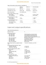
Input and output specifications
Table 25: Input specifications
Number of inputs
8
Default input allocation
IN1 (supervised)
IN2 (supervised)
IN3 (supervised)
IN4 (non-supervised)
IN5 (supervised)
IN6 (supervised)
IN7 (supervised)
IN8 (non-supervised)
Start extinguishing manual call point
Hold extinguishing manual call point
Abort extinguishing manual call point
Disable extinguishing switch (BS 7273 mode)
Manual-only mode control
Low Pressure indication
Extinguishing Agent Flow
Safety door monitoring
Remote reset
Default input end-of-line (supervised inputs
only)
15 kΩ 5% ¼ W passive end-of-line
Unsupervised inputs resistance values
Activation input value
Deactivation input value
≤
9 kΩ ±10%
> 9 kΩ ±10%
Supervised inputs resistance values
Short circuit
Active
High impedance fault
Standby
Open circuit
≤
6
2 Ω
> 62 Ω to 8 kΩ
> 8 kΩ to 10 kΩ
> 10 kΩ to 21 kΩ
> 21 kΩ
Control panel input current
Standby (with end-of-line)
Activated
Open circuit
Short circuit
1.2 mA nominal
5.3 mA max.
100 µA nominal
5.75 mA max.


