Chapter 2: Installation
20
ZP1-X3E Series Installation Manual
Connecting alarm and fault relays
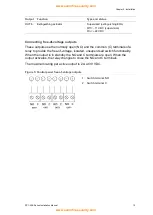
Connect alarm and fault equipment to the ALARM and FAULT relays.
Each potential-free relay output is activated in the corresponding alarm or fault
situation. The fault relay output is activated when there is no fault. This means
that there is a short circuit between the common (C) and normally open (NO)
terminals of the relay.
The maximum contact rating for each relay circuit is 2 A at 30 VDC.
Figure 12: Fault and alarm relay output connections
1. Normally open contact
2. Normally closed contact
3. Common
Connecting expansion boards
Caution:
Risk of equipment damage. Always disconnect the control panel from
the mains power supply before installing an expansion board.
See your expansion board installation sheet for detailed installation information.
Connecting a fire network
Note:
See the 2010-1-NB Network Board Installation Sheet for detailed
installation and connection information.
Each 2010-1-NB network board has two ports. Each port is connected (point to
point) to the corresponding ports of the network board in another control panel.
Figure 13: Network board connections

