Chapter 3: Configuration and commissioning
ZP1-X3E Series Installation Manual
65
Firenet analogue remote node
Use this menu to configure a remote panel out of its 32-node group inside the
250-node network.
To configure the Firenet analogue remote node:
1. Set the display as shown below, and then press Enter.
2. Select a value using the value selection buttons (2 and 4). The Network fault
LED flashes fast to indicate that the Firenet analogue remote node menu is
active.
3. Press Enter.
4. Save your changes.
Advanced configuration options
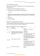
The following table shows the options (available to an advanced configuration
user) for creating an advanced fire network configuration.
Table 19: Advanced configuration options for the fire network
Display
Description
Value
Firenet identifier
0 to 32
0: Stand-alone (no networking)
Default: 0
Firenet group. Allows you to configure
the panel to work in a 32-node network
or in a group of 32 nodes inside a 250-
node network
0000 to 0218
Default: 0000
The number has four digits. Identified
by position, these are: 1234.
Press Up to enter the first two digits of
the number (positions 1 and 2).
Press Down to enter the last two digits
of the number (positions 3 and 4).
Firenet analogue remote node
0000 to 0250
Default: 0000
The number has four digits. Identified
by position, these are: 1234.
Press Up to enter the first two digits of
the number (positions 1 and 2).
Press Down to enter the last two digits
of the number (positions 3 and 4).
Firenet number of nodes [1]
2 to 32
Default: 2


