Chapter 3: Configuration and commissioning
62
ZP1-X3E Series Installation Manual
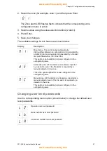
4. Repeat steps 1 to 3 as required for each output (1 to 4) on each installed
module (A, B, C, and D) where a delay is required.
5. Save your changes.
Fire network and repeaters configuration
This section describes how to configure a fire network of conventional control
panels in order to:
• Connect repeaters (any conventional control panel can be configured to
operate as a repeater)
• Create a fire network of conventional control panels, when you need
additional conventional zones in your system
• Create a network including compatible addressable control panels, to add
more features to your fire detection and alarm system (for example, logging
events, complex output activation controlled by the addressable system,
remote monitoring)
When a conventional panel is connected to a fire network it normally displays the
status of one or more panels in the network (depending on repeater configuration
settings). To display information for only that panel, press the Enter key for 3
seconds to provide a temporary, 30-second display of the local status indications.
Basic configuration options
The following table shows the options for creating basic fire network (Firenet)
configurations.
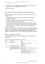
Table 18: Basic configuration options for the fire network
Display
Description
Value
Firenet identifier
0 to 32
0: Stand-alone (no networking)
Default: 0
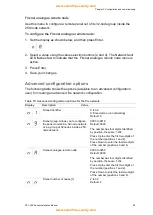
Firenet group. Allows you to
configure the panel to work in a
32-node network or in a group
of 32 nodes inside a 250-node
network
0000 to 0218
Default: 0000
The number has four digits. Identified by position,
these are: 1234.
Press Up to enter the first two digits of the
number (positions 1 and 2).
Press Down to enter the last two digits of the
number (positions 3 and 4).


