


Part Names and Functions
1-4
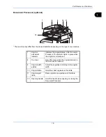
Machine
This chapter explains the names of parts when the machine is used as a fax machine.
For the parts required when functions other than FAX are used, refer to the machine’s
Operation Guide
.
* The machine may differ from the above illustration depending on the type of your machine.
IMPORTANT:
You cannot receive a fax when the main power switch is turned off. To receive faxes with the
power turned off, press the
Power
key on the operation panel.
1
5
4
6
3
2
1
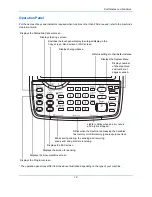
Operation panel
Perform the fax operation with this panel.
2
Main power
switch
Set this switch to the ON (|) side when
performing the fax or copier operation. The
touch panel lights to enable operation.
3
MP (Multi
Purpose) tray
Set the paper in this tray when using a type of
paper other than the cassette (e.g., when
using special paper).
4
LINE connector
(L1)
Connect the modular cord for the telephone
line to this connector. This connector is Port 1.
5
LINE connector
(L2)
If you install 2 optional FAX Kits (Dual FAX
option), you can use Port 2. Connect the
modular cord for the telephone line to this
connector.
6
TEL connector
(T1)
When using a commercially available
telephone set, connect the modular cord to
this connector.
Summary of Contents for CD 1435
Page 1: ...CD 1435 1445 1455 1465 1480 Manual User CDC 1930 1935 1945 1950 Faxsystem V ...
Page 2: ......
Page 18: ...xvi ...
Page 24: ...Part Names and Functions 1 6 ...
Page 136: ...FAX Operation Advanced 4 68 ...
Page 188: ...Setup and Registration 6 40 ...
Page 206: ...Internet Faxing i FAX Option 8 14 ...
Page 214: ...About Network FAX 9 8 ...
Page 242: ...Appendix 20 ...
Page 247: ...MEMO ...
Page 248: ...A1 ...
Page 249: ......
Page 250: ...TA Triumph Adler GmbH Ohechaussee 235 22848 Norderstedt Germany ...