


Version 160624
Page 44
Pin
Description
16
Status 3. Low when format 3 (TOSLINK) is selected.
17
Status 4. Low when format 4 (16 Channel Digital) is selected.
18
Status 5. Low when format 5 (USER 1) is selected.
19
Status 6. Low when format 6 (USER 2) is selected.
20
Status 7. Low when format 7 (8 Channel Analog) is selected.
21
Status 8. Low when format 8 (NON/SYNC) is selected.
22
Status 9. Low when format 9 (AUX) is selected.
23
Status 10. Low when format 10 (MIC) is selected.
24
Mute Status. Low when the system is muted.
25
Unused. Make no connection to this pin.
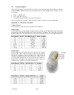
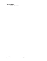
RS-232 Interface
The RS-232 interface appears on a DE9F connector on the rear panel. The connector is wired as a DCE device.
A command interpreter accepts ASCII commands (described in Appendix B) over the RS-232 and Ethernet
interfaces. The RS-232 port operates at 38.4kbps, 8N1 (8 data bits, no parity, 1 stop bit), hardware handshake.
In most situations, no handshake is required, and the RTS and CTS pins can be left open. The USL supplied
ferrite block should be clipped on to the cables adjacent to the connectors to comply with FCC and CE emission
requirements.
Pin
Description
1
DCD – Internally connected to pins 4 and 6. Does not need to be connected in most cases.
2
TXD – The JSD-100MA transmits data on this pin.
3
RXD – The JSD-100MA receives data on this pin.
4
DTR – Internally connected to pins 1 and 6. Does not need to be connected in most cases.
5
GND – Signal ground.
6
DSR – Internally connected to pins 1 and 4. Does not need to be connected in most cases.
7
CTS – The JSD-100MA holds off transmitting data if the device connected to the JSD-100MA
drives this pin low. Data transmission is resumed when this pin is driven high. The pin is pulled
high in the JSD-100MA so the pin can be left open in most cases.
8
RTS – The JSD-100MA drives this pin low when it is not ready to receive data and drives it high
when it is ready to receive data. In most cases this pin can be left open.
9
RI – The JSD-100MA provides a current limited (900mA) +5V to drive external equipment on this
pin.
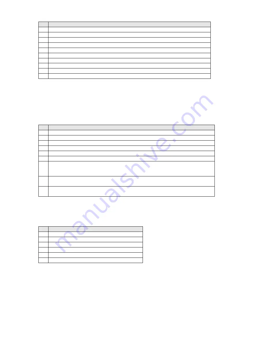
RS-485
A RS-485 bus is used to interface the JSD-100MA to other USL devices such as the JSDV-100 remote volume
control (discussed earlier in this manual). The USL supplied ferrite block should be clipped on to the cables
adjacent to the connectors to comply with FCC and CE emission requirements.
Pin
Description
1
Current limited (100mA) +5V to drive external devices.
2
RS-485 Signal Ground.
3
RS-485 Data.
4
RS-485 Data Not.
5
No Connect.
6
No Connect.