


Version 160624
Page 8
4.2
Block Diagrams
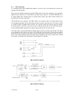
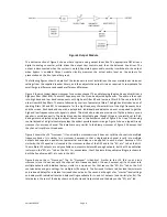
The following pages contain simplified block diagrams to assist the user in understanding the structure and
operation of the JSD-100MA.
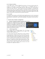
Figure 1 shows a simplified overall view of the JSD-100MA system. Two channel analog inputs are converted to
digital. There is a "simple matrix" in the DSPs that can convert stereo inputs to 5.1. The JSD-100MA allows for a
16 channel digital input. All these signals are routed through various input select switches based on the
selected format, then sent to the DSPs.
DSP1 handles the screen channels, while DSP2 handles the surround channels. All channels except LFE go
through a graphic equalizer. The LFE channel goes through a parametric equalizer and a 125Hz low pass filter
as specified by SMPTE EG0432-2-2006. Similarly, the surround channels go through a graphic equalizer.
Provision is made to select the source of the surround channels (discrete channels or synthesized sources).
Surround delays (individual delays for each channel pair) are added to the surround channels.
All channels have a synchronization delay to compensate for projector and other system delays. Sync delays
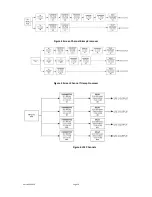
are configurable for each format. Note that the JSD-100MA can support multiple LFE and surround outputs.
Because of this, the LFE parametric equalizer is actually located in the crossover section of the DSP and GUI
XO, Etc tab. Similarly, individual Ls/Rs output delays are also available in the crossover section where multiple
Ls/Rs outputs are available. See the following crossover figures for more detail.
Figure 1 Audio Processing
Figure 2 Audio Processing


