


Operating Instructions
Functional Manual
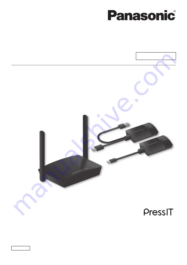
Wireless Presentation System
For business use
Model No.
TY-WPS1
WPS Basic Set
TY-WPB1
WPS Transmitter
TY-WPBC1
WPS USB-C Transmitter
TY-WP2B1
WPS Transmitter Set
TY-WP2BC1
WPS USB-C Transmitter Set
*
WPS is an abbreviation of “Wireless Presentation System”.
*
PressIT is a nickname for “Wireless Presentation System”.
English
Thank you for purchasing the Panasonic product.
•Please read these instructions before operating this product and retain them for future reference.
•
Be sure to read “Safety Precautions” (page 2 to 3) before use.
•These Operating Instructions are shared by TY-WPS1, TY-WP2B1, TY-WPB1, TY-WP2BC1 and TY-WPBC1.
DA0920TS0 -PB
DPQP1359ZA/X1


