80
4
SETTINGS AND CALIBRATIONS
80
SE
TTINGS
A
ND CAL
IB
R
ATIONS
Chapter
4
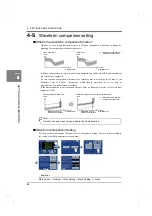
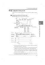
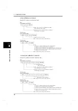
- Reference; Back, or Relative Comparison in use
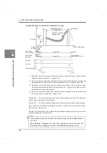
t1: Delay time between the instant when the Start input is turned ON and the instant when all
outputs but Run are turned OFF ... Approx. 5ms
t2: Delay time between the instant when the Start input is turned OFF and the instant when the
measurable section is started. It varies depending on the time of crossing the Start Load.
t3: Delay time between the instant when the measurement is stopped (the Stop input is turned
ON) and the instant when the Result output is turned ON ... Approx. 50ms (However, there
are differences between measurements.)
t4: Delay time between the instant when the Result output is turned ON and the instant when
the Complete output is turned ON ... Approx. 30ms
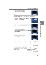
- Turning OFF
→
ON the external input signal “Start” releases the hold, and turns OFF all outputs
but Run. (Reset operation by the Start input)
- Turning OFF
→
ON the Stop signal or taking data of 2048 points turns ON the Complete signal.
- After completion of measurement, judgment is made by scanning the waveform from its front,
and HI or LO or OK turns ON.
- OK turns ON if the Compare Area is passed through during measurement and the result is not LO
or HI after completion of measurement.
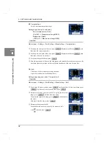
Load
Compare Area
Wave Result
Start load
Stop input
OFF
ON
Start input
OFF
ON
Complete output OFF
ON
OK output
Wave Result
LO or HI output
Measurement section
Calculating
Output OFF
HI output
Output OFF
OK is output if
Result is not LO or HI.
t4
t3
t1
t2
Waveform comparison
judgment point
Reset operation
by the Start input
Time or displacement
Sensor
input
value
Result of the
previous
measurement
Result of the
previous
measurement
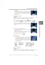
If the measurement does not reach the Compare Area, all Wave Result outputs
turn OFF.
When Relative Comparison is used, if the measurement does not reach the
Reference Point, no judgment is made. (All Wave Result outputs are OFF.)
Point
Summary of Contents for DeviceNet F381A
Page 1: ...15APR2013REV 3 10 DYNAMIC FORCE PROCESSOR F381A OPERATION MANUAL ...
Page 9: ...Contents VIII Contents VIII M E M O ...
Page 34: ...25 2 INSTALLATION AND CONNECTION 25 INSTALLATION AND CONNECTION Chapter 2 M E M O ...
Page 147: ...138 8 SPECIFICATIONS 138 SPECIFICATIONS Chapter 8 8 2 Outside dimensions Unit mm ...
Page 164: ......

