12
2
INSTALLATION AND CONNECTION
12
INST
ALLATION AND CONNECT
ION
Chapter
2
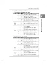
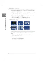
- Option (Displacement input: Pulse input (line driver) [LDI])
Type
Pin No.
Signal
Use
Load input
1
+EXC
Terminal to supply the voltage of the strain gauge type sensor.
CIN of the strain gauge type sensor.
2
-SIG
Terminal to input the signal of the strain gauge type sensor.
Connect –OUT of the strain gauge type sensor.
3
-EXC
Terminal to supply the voltage of the strain gauge type sensor.
Connect -IN of the strain gauge type sensor.
4
+SIG
Terminal to input the signal of the strain gauge type sensor.
COUT of the strain gauge type sensor.
5
F.G.
Frame ground terminal to connect the shielded wire of the strain gauge
type sensor connecting cable.
Analog
monitor
output
6
VOL
OUT
Terminal to output voltage proportional to the input of the strain gauge
type sensor. (Approx. 2V per 1mV/V)
Connect a pen recorder, etc., for simply monitoring the input of the
strain gauge type sensor.
7
GND
Ground terminal of VOL OUT.
Displacement
input
(LDI)
8
F.G.
Frame ground terminal to connect the shielded wire of the pulse output
sensor connecting cable.
9
A+
Terminal to input the A+ (PCA,
φ
A) output of the pulse output sensor.
Connect the A+ (PCA,
φ
A) output of the pulse output sensor.
10
A-
Terminal to input the A- (A/, A, *PCA,
φ
A) output of the pulse output
sensor.
Connect the A- (A/, A, *PCA,
φ
A) output of the pulse output sensor.
11
B+
Terminal to input the B+ (PCB,
φ
B) output of the pulse output sensor.
Connect the B+ (PCB,
φ
B) output of the pulse output sensor.
12
B-
Terminal to input the B- (B/, B, *PCB,
φ
B) output of the pulse output
sensor.
Connect the B- (B/, B, *PCB,
φ
B) output of the pulse output sensor.
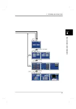
Please calibrate it after wiring the sensor.
See the following:
Load:
Displacement:
Attention
Summary of Contents for DeviceNet F381A
Page 1: ...15APR2013REV 3 10 DYNAMIC FORCE PROCESSOR F381A OPERATION MANUAL ...
Page 9: ...Contents VIII Contents VIII M E M O ...
Page 34: ...25 2 INSTALLATION AND CONNECTION 25 INSTALLATION AND CONNECTION Chapter 2 M E M O ...
Page 147: ...138 8 SPECIFICATIONS 138 SPECIFICATIONS Chapter 8 8 2 Outside dimensions Unit mm ...
Page 164: ......

