62
4
SETTINGS AND CALIBRATIONS
62
SE
TTINGS
A
ND CAL
IB
R
ATIONS
Chapter
4
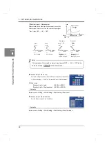
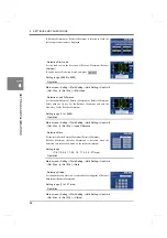
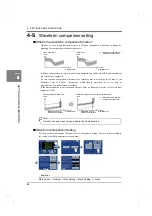
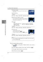
- Load HI/LO Limit
Set the range of load in which the judgment point is judged to be OK.
Setting range (-9999 to +9999: The range is the same
for the HI limit and LO limit.)
Operation
* Setting the HI limit < the LO limit is unacceptable.
Main screen
→
Setting
→
Work Setting
→
Hold Setting
→
Load HI/LO Limit
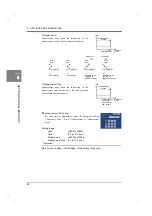
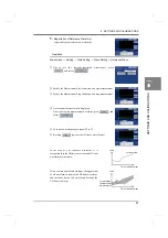
- Displacement HI/LO Limit
(only when the X-axis represents displacement)
Set the range of displacement in which the judgment point is judged
to be OK.
Setting range
Displacement (Front):
(0 to 2047
×
Measurement Length/2000)
Displacement (Back):
(-2047 to 0
×
Measurement Length/2000)
* Setting the HI limit < the LO limit is unacceptable.
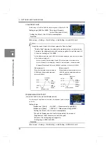
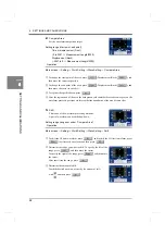
* When End Displacement in Use Hold is selected, the screen of
Displacement HI/LO becomes a numeric keypad.
Moreover, the setting range changes too.
Operation
Setting range (-9999 to 32000)
Main screen
→
Setting
→
Work Setting
→
Hold Setting
→
DPM HI/LO Limit
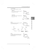
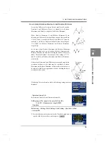
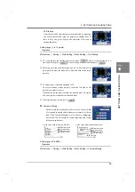
About the Load HI and LO Limit set values for “Peak to Peak”
“Peak to Peak” judgment is made by the maximum value – minimum value.
Therefore, the judgment value will never be negative. So, set the Load HI/
LO Limit in the range of 0 to 9999.
On the Main screen, the Load HI/LO Limit is offset-displayed (red line) on the basis
of the minimum value (=0).
Value of Load HI Limit display = Load HI Limit set value + minimum value
Value of Load LO Limit display = Load LO Limit set value + minimum value
Example) When Load HI Limit is 30.00kN, and Load LO Limit is 10.00kN,
[Measurement 1]
[Measurement 2]
When the detected minimum value is
When the detected minimum value is
0.00kN, and the detected maximum
10.00kN, and the detected maximum
value is 40.00kN
value is 50.00kNN
40.00
30.00
10.00
0.00
Minimum value
Maximum
50.00
40.00
20.00
10.00
Minimum value
Maximum
Load
Load
display
HI Limit
display
LO Limit
value
value
Load
Load
display
HI Limit
display
LO Limit
Point
Summary of Contents for DeviceNet F381A
Page 1: ...15APR2013REV 3 10 DYNAMIC FORCE PROCESSOR F381A OPERATION MANUAL ...
Page 9: ...Contents VIII Contents VIII M E M O ...
Page 34: ...25 2 INSTALLATION AND CONNECTION 25 INSTALLATION AND CONNECTION Chapter 2 M E M O ...
Page 147: ...138 8 SPECIFICATIONS 138 SPECIFICATIONS Chapter 8 8 2 Outside dimensions Unit mm ...
Page 164: ......

