


24
2
INSTALLATION AND CONNECTION
24
INST
ALLATION AND CONNECT
ION
Chapter
2
4.
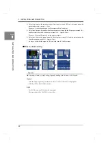
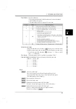
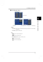
Go to the COM. Check screen under Self-Check.
Operation
Main screen
→
Setting
→
First Setting
→
System Setting
→
Self-Check
→
COM. Check
5.
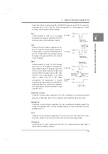
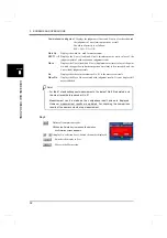
Transmit any statement from the equipment connected.
(Check only when the Communication Mode is Normal.)
The data received by the F381A is displayed.
Check that the transmitted data is displayed.
If the Parity or Frame lights in red and the data is not displayed properly, go back to Step 1
or 2, and check again the cable or communication settings.
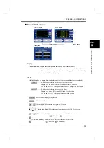
6.
Press the Trns. Key.
Pressing the Trns. key transmits the statement having the same contents as the display
reading.
Check that it can be received properly on the side of the equipment connected.
If not, go back to Step 1 or 2, and check again the cable or communication settings.
7.
Set again the Communication Mode according to application.
Operation
Main screen
→
Setting
→
First Setting
→
Com. Setting
→
Com. Mode
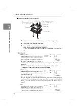
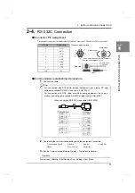
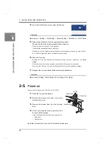
2-5.
Power-on
Connect the DC power cord. (24V DC (±15%) 24W)
1.
Check that no power is applied.
2.
Remove the screws (two), and remove the
terminal block cover.
3.
Remove the screws (two) from the terminal
block.
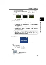
4.
Fit the crimp contacts to the screw holes, and
fix them with the screws.
Carry out wiring from the silk-screen-printed side.
+: Red screw
-
: Black
screw
Install the terminal block cover, and fix it with the screws (two).
Within 6mm
Red screw
Black screw
DC IN
+
-
G
Summary of Contents for DeviceNet F381A
Page 1: ...15APR2013REV 3 10 DYNAMIC FORCE PROCESSOR F381A OPERATION MANUAL ...
Page 9: ...Contents VIII Contents VIII M E M O ...
Page 34: ...25 2 INSTALLATION AND CONNECTION 25 INSTALLATION AND CONNECTION Chapter 2 M E M O ...
Page 147: ...138 8 SPECIFICATIONS 138 SPECIFICATIONS Chapter 8 8 2 Outside dimensions Unit mm ...
Page 164: ......