23
2
INSTALLATION AND CONNECTION
23
INSTALLAT
ION AND CONNECTION
Chapter
2
2-4.
RS-232C Connection
■
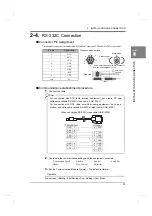
Connector Pin Assignment
The adaptable connector is manufactured by Hosiden Corporation TCP8080-015267 or equivalent.
■
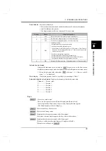
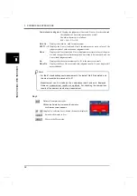
Communication establishment procedure
1.
Connect the cable.
2.
Coordinate the communication settings with the equipment connected.
- Transmission Speed
- Data Bit
- Stop Bit
- Parity Bit
- Header
- Flow Control
- Delimiter
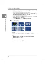
3.
Set the Communication Mode to Normal.
(
The default is Normal.
)
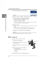
Operation
Main screen
→
Setting
→
First Setting
→
Com. Setting
→
Com. Mode
Insert
6
7
8
5
4
2
1
3
Wire connection surface
Side view
Metal case
Plastic cover
Secure with
Fit the metal cases into the Din connector,
and cap with the plastic covers.
Pin No.
Signal name
1
DCD
2
RXD
3
TXD
4
DTR
5
GND
6
DSR
7
RTS
8
CTS
Case
F.G.
hardware
For connection with DTE (data terminal equipment), such as a PC, use
optionally available RS-232C cross cable (CA81-232X).
For connection with DCE (data circuit-terminating equipment), such as a
modem, use optionally available RS-232C straight cable (CA81-232S).
Point
DCD
DSR
RXD
TXD
DTR
GND
RTS
CTS
1
6
2
3
4
5
7
8
4
3
2
1
6
5
8
7
9
DTR
TXD
RXD
DCD
DSR
GND
CTS
RTS
RI
TCP8080-015267
D-Sub 9pin
When connecting RS-232C cross cable [CA81-232X].
Summary of Contents for DeviceNet F381A
Page 1: ...15APR2013REV 3 10 DYNAMIC FORCE PROCESSOR F381A OPERATION MANUAL ...
Page 9: ...Contents VIII Contents VIII M E M O ...
Page 34: ...25 2 INSTALLATION AND CONNECTION 25 INSTALLATION AND CONNECTION Chapter 2 M E M O ...
Page 147: ...138 8 SPECIFICATIONS 138 SPECIFICATIONS Chapter 8 8 2 Outside dimensions Unit mm ...
Page 164: ......


