UniPOS
Wireless Fire Alarm Control Panel VIT 01
Instruction manual
Page 35
Revision 10/02.17
Pages 51
12.4.3.2. Devices
By buttons
and
of the main screen proceed to test mode and setting up of the
devices in the network.
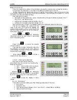
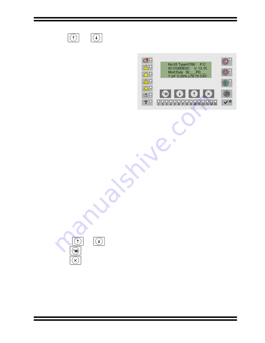
For each device, registered in the system it
is shown the condition, the measured values and
the basic parameters.
The first line indicates the number (the
address), the type of the device and “parent” in
the network.
Example: “P:C” means detector with
address 03 communicate directly with the
(C)ontrol panel (without retransmission of the
signal trought routers )
.
The second line
– its identical number and
the software version.
The third line
– the mode of operation and
the
status.
In
the
status
is
displayed
corresponding index:
S
– signal „Fire Condition” of optical smoke measurement;
T
– signal „Fire” of temperature measurement;
B
– low battery (failed back-up battery supply to the router);
P
– open detector (failed user supply voltage to the peripheral devices to router);
D
– normal operation of the measuring system (registration trough this router is enabled);
A
– signal „Fire condition” by the rise of temperature;
X
– the measured value is out if the predefined parameters;
M
– low battery in the back up power source(failed mains supply of router);
On the last line are shown the measured values from the device. They are different for the
different types and have the following meanings:
T
–
measured temperature;
C
–smoke concentration;
L
– quality of the radio connection, as the first number refers to the Control Panel, and a
second refers to the end device;
S
– number of the devices, connected directly to the router;
the last value is the voltage of the supplying battery.
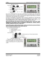
Active buttons are:
buttons
and
- for showing of the registered devices;
button
- transition to a menu, describing the device shown;
button
- exit to menu
„Registration”.


