www.ultratecfx.com
28
Data In / Data Out
These are the communications connectors (5 pin XLR). Data In is Male, Data Out is Female.
Slaves can be daisy chained in any order on the data line, however the connections must run Out to
In to Out to In etc. The data signal is rebroadcast at each remote to improve performance and dis-
tance.
SureFire Digital Airburst Slave Module
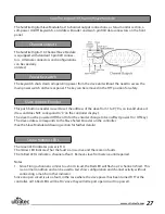
The 48 channel Digital Airburst Slave has 16 output connections, a status monitor section, a soft-
power On/Off keyswitch and two 5 pin XLR data connectors on the front panel.
Channel Outputs
Power Keyswitch
Slave Address Encoder
The Digital Airburst Slave is equipped with standard RJ style phone connectors (6 pin). Each connec-
tor has 3 circuits grouped (1&2), (3&4), (5&6).
The keyswitch shuts down all operating power from the slave unit without the need to access the
main power switch on the rear panel. The key can be removed in the ‘Off’ position for safety.
48 Channel Slave Modules have encoders mounted on the back panel. The encoders should be set
to occupy 3 consecutive numbers (ie. 123 or 234, etc).
Status Monitor LEDs
The Digital Airburst Slave integrates 3 separate DS-16 circuit boards and monitors the status of each
board on a separate LED section.
The 3 Green LED indicates power is ‘On’ for each board..
The 3 Yellow LED indicates that the fault scan is active and there are no faults at each board.
The 48 Red LED’s indicate a channel at fault. Ensure that nothing is connected to this channel output
until the fault has been corrected.
Notes
1. Since Firing a channel is similar to a short circuit, the Red LED will flash as it’s channel is fired. This
is a normal condition and can be used to test show configuration and channel activity without
connecting a match or other indicator.
2. Since an open circuit is also a fault, in the case where the slave power has been turned ‘Off’ at the
controller, all 48 Red LED’s will be ‘On’ since they will all report open circuit (no power).


