www.ultratecfx.com
27
SureFire Digital 16 Channel Slave Module
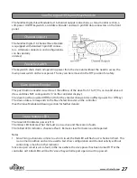
The SureFire Digital Slave Module has 16 channel output connections, a status monitor section, a
soft-power On/Off keyswitch, an Address Encoder and two 5 pin XLR data connectors on the front
panel.
Channel Outputs
The SureFire Digital 16 Channel Slave Module
is equipped with standard 3 pin XLR connec-
tors. Alternate connectors and configurations
can be specially
ordered.
Power Keyswitch
The keyswitch shuts down all operating power from the slave unit without the need to access the
main power switch on the rear panel. The key can be removed in the ‘Off’ position for safety.
Slave Address Encoder
This push button encoder is used to set the address of the slave from 1 to 9 (‘0’ is an invalid slave ad-
dress and does NOT correspond to ‘0’ on the controller display).
The slave must be powered Off then On for the encoder change to be in effect (power On / Off key).
The slave address corresponds to the Slave Select Encoder on the controller.
(See the Slave Module Addressing section for further details).
Status Monitor LEDs
The Green LED indicates power is ‘On’.
The Yellow LED indicates That the fault scan is active and there are no faults.
The 16 Red LED’s indicate a channel at fault. Remove slave from service until repaired.
Notes
1. Since Firing a channel is similar to a short circuit, the Red LED will flash as it’s channel is fired. This
is a normal condition and can be used to test show configuration and channel activity without
connecting a match or other indicator.
Since an open circuit is also a fault, in the case where the slave power has been turned ‘Off’ at the
controller, all 16 Red LED’s will be ‘On’ since they will all report open circuit (no power).


