V02.00 | 2020/08
21
6.3
Connecting digital sensors and actuators
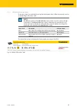
The device has two 5-pin M12 plug connectors for connecting digital sensors and actuators.
Fig. 10: M12 plug connectors for connecting digital sensors and actuators
NOTE
When operating via PoE (Power over Ethernet) the digital channels cannot be used
as outputs.
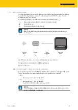
Connect sensors and actuators to the device as per the following pin assignment (max.
tightening torque 0.8 Nm).
4
1
3
2
5
v
1
= Vaux
2
= DXP1 / DXP3
3
= GND
4
= DXP0 / DXP2
5
= FE
DXP0...DXP3
5 FE
4 BK
1 BN +
3 BU –
3 BU –
2 WH
v
DXP0...DXP3
Sensor
or
Actuator
Sensor
or
Actuator
Fig. 11: Connections for digital sensors and ac-
tuators – pin assignment
Fig. 12: Connections for digital sensors and ac-
tuators – wiring diagram
Summary of Contents for TN-UHF AUS-CDS Series
Page 1: ...Your Global Automation Partner Instructions for Use TN UHF CDS UHF Read Write Head ...
Page 2: ...2 Hans Turck GmbH Co KG T 49 208 4952 0 F 49 208 4952 264 more turck com www turck com ...
Page 97: ...V02 00 2020 08 97 Transfer the mapping to the POU Fig 94 Transferring the mapping to the POU ...


