V02.00 | 2020/08
33
7.1.6
Setting antenna power
The antenna power of the read/write head can be set for the specific application. The radiated
power for the integrated antenna can be entered directly in the DTM. The power must be
calculated for external antennas.
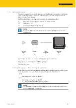
The following parameters must be used to calculate the radiated power (P
ERP
):
P
cond
Power to be output at the TNC socket of the read/write head
dB
Cable attenuation
G
HW
Antenna gain of the external antenna
NOTE
Refer to the data sheets of the components used for the cable attenuation and
antenna gain.
BUS
ERR
RUN
APP
LAM
PWR
RFON
DATA
DIAG
USER
Conducted
power
P
cond
Cable
attenuation
dB
Antenna
gain
G
HW
Radiated
power
P
ERP
Antenna
Fig. 25: Power calculation – relevant variables (schematic representation)
The power can be calculated with the following formula:
P
ERP
= G
HW
- dB + P
cond
Setting antenna power – Restrictions of radio regulations
Some national regulations restrict the degree of freedom available for creating an RFID system.
You as the operator are responsible for ensuring that regulations are observed.
n
ETSI
– Radiated power P
ERP
: Max. 33 dBm ERP
n
FCC
– Radiated power P
ERP
: Max. 36 dBm EIRP
– P
cond
: Max. 30 dBm with antenna gain G
HW
≤ 6 dbi
NOTE
The DTM indicates impermissible configurations with an exclamation mark. A trans-
mission to the device is prevented.
Summary of Contents for TN-UHF AUS-CDS Series
Page 1: ...Your Global Automation Partner Instructions for Use TN UHF CDS UHF Read Write Head ...
Page 2: ...2 Hans Turck GmbH Co KG T 49 208 4952 0 F 49 208 4952 264 more turck com www turck com ...
Page 97: ...V02 00 2020 08 97 Transfer the mapping to the POU Fig 94 Transferring the mapping to the POU ...


