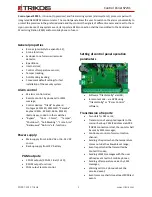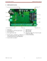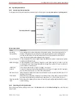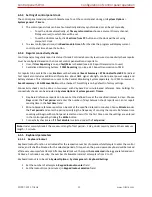
Control panel SP231
Control panel structure
©1997-2015 Trikdis
10
www.trikdis.com
4.1
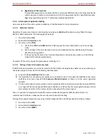
Purpose of terminals
Main supply terminal block
Terminal
Description
16V AC
16-24V DC
Main supply contacts shall be connected either to 16 – 18 V AC or 16 – 24 V DC
source.
Back-up supply port
Terminal
Description
-BAT+
Port for connecting the 12 V back-up battery.
Terminal block for peripherals
Terminal
Description
PGM1-PGM3
Programmable operation output terminals for connecting the indicators and
remotely controlled equipment.
BELL+, BELL-
Contacts for connecting the siren.
AUX+
Positive 13.6 V DC supply terminal for keyboard(s), indicators and sensors.
C
Negative supply terminal for keyboard(s), indicators and sensors.
YEL
Peripherals (e.g., keyboard) YEL circuit contact (yellow wire).
GRN
Peripherals (e.g., keyboard) GRN circuit contact (green wire).
MCI
Data bus contact for iButton key code reader and/or other report transmission
devices (e.g., radio transmitter).
ZN1-ZN8
Contacts for connecting the sensor control circuits. The contact ZN8 can be used for
connecting the 2-wire smoke detectors.
1-wire bus terminal block
Terminal
Description
LED
The contact for connecting the premises protection mode indicator, e.g., iButton
key reader LED cathode (-) (PGM5).
+5V
Positive 1-wire devices 5V DC supply contact.
1W
1-wire devices data circuit contact (iButton keys, temperature sensors)
C
Negative 1-wire devices supply contact.
4.2
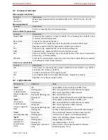
Light indication
LED indicator
Operation
Value
“NET2”
shows log on
to GSM network
statuses using card
SIM2
Off
Not available or impossible to read SIM2 card.
Flashing green
SIM2 card registration in GSM network in progress.
Solid green
SIM2 card is registered in GSM network.
Frequently flashing green
SIM2 card PIN code error.
Flashing red
Number of flashes (below 10) show GSM field strength.
“NET1”
shows log on
to GSM network
statuses using card
SIM1
Off
Not available or impossible to read SIM1 card.
Flashing green
SIM1 card registration in GSM network in progress.
Solid green
SIM1 card is registered in GSM network.
Frequently flashing green
SIM1 card PIN code error.
Flashing red
Number of flashes (below 10) show GSM field strength.
“Data”
shows broadcasting
Solid green
The control panel memory contains unsent reports.
Flashing green
Transmission of reports to indicated addresses.
“PWR”
shows power
supply status,
programming
mode.
All are off
Power is off or battery voltage is lower than 9.5 V.
Flashing green
Supply voltage is sufficient.
Flashing red
Low supply voltage (< 11.5 V).
Flashes green and red in
turns
Start-up of the control panel operation software
(duration approx. 7 sec.).


