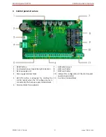
Control panel SP231
System installation
©1997-2015 Trikdis
16
www.trikdis.com
5.4
Connection of smoke detectors
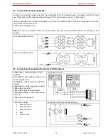
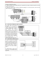
In order to connect the control circuit of the smoke detector to the selected input, it is necessary that this input
was “Fire” zone, i.e. this input must be with the set “Fire” zone function (see 6.7.1 “Main zone ”).
When connecting the four-wire smoke detector circuit to the selected PGM output, this output shall be with the
set Fire reset function (see 6.13 “
PGM output configuration”).
ZN8 input can be dedicated namely for connecting the two-wire smoke detectors (see 6.7.1.2 “Setting of Fire
zones”).
Four-wire smoke detectors
Two-wire smoke detectors
5.5
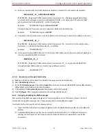
Connection of equipment terminals to PGM outputs
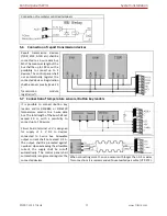
PGM1-PGM3 - three terminals of open
collector,
BELL-(PGM4) - open collector terminal for
connecting the siren,
LED (PGM5) - collector terminal with 5K1
resistor.
Regarding all possible operation modes of
PGM outputs see 6.13.1 “
PGM output operation descriptions”.
Regarding changing of initial output values
see 6.13 “
PGM output configuration”.
Connection of sirens
PGM initial settings
1.
Remote Control
2.
Remote Control
3.
Remote Control
4.
Bell
5.
System State
Connection of alarm (controlled) devices

